Un horno puede tener suficiente energía de calentamiento en papel y aún así ser difícil de construir, cablear o mantener. Una razón que se pasa por alto es la ubicación de los terminales. Si las conexiones se colocan a ambos lados de la cámara, los técnicos necesitan acceso a ambas paredes del horno. Si todas las conexiones se llevan a un lado, el gabinete eléctrico se vuelve más fácil de centralizar, pero la estructura del elemento y el espaciado de los terminales se vuelven más complejos.
Elegir entre de un solo extremo y de dos extremos elementos calefactores de carburo de silicio por lo tanto, no es sólo una decisión de producto. Afecta las aberturas de las paredes del horno, las rutas de cableado, la autorización de mantenimiento, el diseño de soporte, la expansión térmica, los procedimientos de reemplazo y el espacio utilizable alrededor del equipo.
Esta guía explica cómo los diseñadores de hornos, ingenieros de mantenimiento y compradores industriales pueden comparar ambos acuerdos antes de aprobar un horno nuevo o un elemento de reemplazo.
Tabla de contenidos
Decisiones clave antes de seleccionar un diseño de elemento
- Compruebe si el personal de mantenimiento puede llegar con seguridad a uno o ambos lados del horno.
- Distinguir la ubicación del terminal de la geometría del elemento; Los terminales del mismo lado no siempre indican la misma estructura interna.
- Confirme la posición de la zona caliente antes de planificar las aberturas de las paredes del horno.
- Revise el número, diámetro y espaciado de todos los orificios requeridos.
- Incluya abrazaderas de terminales, tiras conductoras, cables, cubiertas y espacios libres eléctricos en el diseño.
- Evalúe cómo el elemento puede expandirse sin verse restringido.
- Confirme si un elemento defectuoso se puede quitar sin desmontar el equipo adyacente.
- Compare la resistencia, el voltaje, la potencia y la disposición del circuito antes de tratar dos estructuras como intercambiables.
- Prepare un dibujo dimensionado en lugar de realizar pedidos a partir del nombre de un modelo o fotografía.
- Considere el acceso de mantenimiento futuro durante la etapa inicial de diseño del horno.
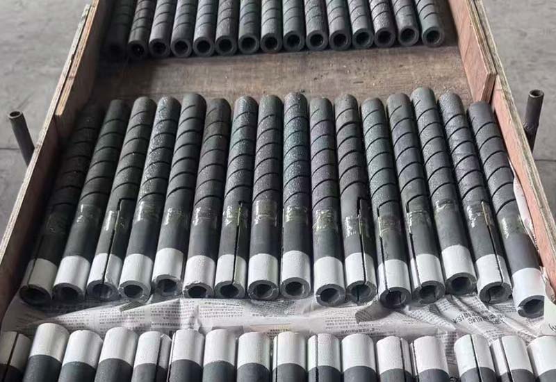
Los compradores pueden revisar primero lo disponible elementos calefactores de carburo de silicio comprender las diferencias entre estructuras rectas, con ranuras en espiral, de un solo extremo, en forma de U y de múltiples patas.
Lo que realmente significan un solo extremo y un doble extremo
Los términos describen la ubicación de las conexiones eléctricas, pero no proporcionan una especificación completa.
Estructura de un solo extremo
Un elemento de un solo extremo lleva ambas conexiones eléctricas al mismo lado del horno. La corriente viaja por un camino activo y regresa por otro camino incorporado a la estructura del elemento.
La principal ventaja de la instalación es el acceso unilateral. La pared opuesta del horno puede permanecer libre de terminales, tiras conductoras, cubiertas protectoras y actividades de mantenimiento.
El Elemento calefactor de carburo de silicio tipo UX utiliza una configuración de un solo extremo destinada a instalaciones donde el cableado debe permanecer en un lado. Una ranura en espiral Varilla de carburo de silicio tipo SGR también coloca su conexión eléctrica en un extremo mientras utiliza una estructura de sección activa diferente.
Estos dos ejemplos ilustran un punto importante: “un solo extremo” identifica la disposición de conexión, no una forma universal o un nivel de rendimiento.
Estructura de doble extremo
Un elemento de doble extremo tiene una conexión eléctrica en cada extremo. Una varilla recta normalmente pasa a través de la cámara, con terminales que se extienden fuera de las paredes opuestas del horno.
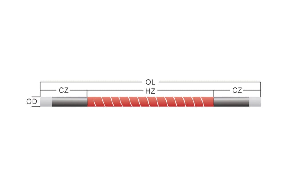
El Elemento calefactor SiC tipo DH es un ejemplo sencillo. Su sección de calefacción central se encuentra entre dos extremos fríos, mientras que las conexiones eléctricas se encuentran en lados opuestos.
Un ranurado en espiral Varilla de carburo de silicio tipo SG también utiliza conexiones en ambos extremos, pero su geometría de sección activa difiere de una varilla recta simple.
Para ambas disposiciones, la elección final debe basarse en las dimensiones, la resistencia, la construcción del horno, las condiciones de funcionamiento y el diseño del circuito, no sólo en la ubicación del terminal.
La diferencia de diseño principal
La siguiente tabla compara las implicaciones prácticas de la instalación elementos calefactores de carburo de silicio con conexiones unilaterales o bilaterales.
| Factor de diseño | Arreglo de un solo extremo | Arreglo de doble extremo |
|---|---|---|
| Ubicación de la terminal | Ambas conexiones por un lado | Una conexión a cada lado |
| Acceso al horno | Principalmente unilateral | Normalmente se requiere acceso por ambos lados |
| Pared opuesta | Puede permanecer libre de terminales externos | Requiere apertura y zona terminal |
| Enrutamiento eléctrico | Concentrado por un lado | Distribuido por dos lados |
| Densidad terminal | Más alto cerca del lado de conexión | Inferior en cada lado individual |
| Dirección de eliminación | Generalmente retirado de un lado | Puede requerir espacio libre a lo largo del eje del elemento |
| Construcción de elementos | Requiere una ruta integrada de retorno de corriente | La corriente generalmente viaja de un extremo a otro |
| Orificios del horno | Depende de la estructura específica de un solo extremo | Generalmente aberturas alineadas en paredes opuestas |
| Planificación del mantenimiento | Acceso centralizado pero conexiones abarrotadas | Requisito de acceso más amplio pero distribución terminal más sencilla |
| Idoneidad de modernización | Útil cuando la parte trasera es inaccesible | Lógico cuando el horno original ya tiene aberturas opuestas |
Ninguno de los diseños es automáticamente más eficiente ni duradero. La disposición correcta es la que se adapta mecánicamente al horno, coincide con el sistema eléctrico y permanece en servicio durante toda su vida útil.
Comience con el mapa de acceso al horno
Antes de seleccionar elementos calefactores de carburo de silicio, extraiga el horno y el equipo circundante desde arriba. Marque todas las áreas a las que los técnicos puedan llegar de forma segura.
El mapa de acceso debería mostrar:
- Paredes del horno y espesor del aislamiento
- Gabinetes de control
- Conductos de escape
- Gas, aire, agua de refrigeración y tuberías de proceso
- Puertas de carga
- Sistemas transportadores o de rodillos
- Columnas estructurales
- Barreras de seguridad
- Pasarelas
- Distancia de eliminación requerida
- Acceso de grúa o elevación
- Zonas de exclusión de superficies calientes
Este dibujo a menudo revela la dirección apropiada antes de que comiencen los cálculos eléctricos.
Cuando el acceso trasero está bloqueado
Se puede instalar un horno cerca de la pared de un edificio, otra línea de producción, un bastidor de servicios públicos o un conducto grande. Incluso si una varilla de doble extremo encaja físicamente, su terminal trasero puede ser imposible de inspeccionar o apretar.
En esa situación, de un solo extremo elementos calefactores de carburo de silicio puede proporcionar una disposición de mantenimiento más práctica. Ambos terminales permanecen visibles desde el lado accesible y el elemento normalmente se puede retirar en la misma dirección.
Sin embargo, el lado accesible debe tener suficiente espacio para dos terminales, conductores flexibles, barreras aislantes, cubiertas protectoras y eliminación completa de elementos.
Cuando ambos lados están abiertos
Un diseño de doble extremo puede ser más sencillo cuando el horno se encuentra en un área de servicio abierta. Las conexiones se pueden distribuir entre paredes opuestas, reduciendo la congestión de terminales a ambos lados.
El equipo de mantenimiento todavía necesita un camino de extracción sin obstáculos. Una varilla larga y recta no se puede quitar simplemente porque se pueda acceder a ambos terminales. La holgura axial disponible debe ser al menos suficiente para el método de extracción aprobado.
Cuando la posición del equipo puede cambiar
También se deben considerar futuros cambios de diseño. Un horno al que se pueda acceder durante la puesta en servicio puede estar rodeado posteriormente por plataformas, colectores de polvo, protecciones o equipos de producción adicionales.
Por lo tanto, los registros de selección deben indicar la dotación mínima de servicio permanente requerida por el elegido elementos calefactores de carburo de silicio.
Las aberturas de pared de horno son parte del diseño de calefacción
Un agujero a través de la pared del horno no es sólo un paso mecánico. Cruza la carcasa exterior, el aislamiento, el revestimiento de la cara caliente, los sellos, los manguitos y, a veces, un límite de control de la atmósfera.
Aberturas opuestas para varillas rectas
Los elementos rectos de doble extremo generalmente requieren aberturas en paredes opuestas. Estas aberturas deben compartir la línea central correcta. Un pequeño error de alineación puede forzar la flexión de una varilla cerámica quebradiza.
El elemento nunca debe usarse como palanca para compensar agujeros desalineados. La alineación debe ser establecida por la estructura del horno y verificada antes de la instalación.
Aperturas unilaterales
De un solo extremo elementos calefactores de carburo de silicio elimine la necesidad de un terminal de elemento en la pared opuesta. Esto puede simplificar el recinto trasero y reducir el número de penetraciones en la pared.
La abertura del lado de conexión aún necesita un diseño cuidadoso. El orificio o manguito debe ajustarse al diámetro especificado, proporcionar el espacio libre requerido, evitar agarrar la sección activa y permitir la instalación sin impacto.
Fuga de calor alrededor de las aberturas
Una abertura innecesariamente grande puede aumentar la radiación y las fugas de aire. Una abertura demasiado apretada puede restringir el movimiento térmico o dañar el elemento durante la instalación.
El objetivo es un espacio libre controlado, no una presión máxima de sellado. Los detalles del sellado dependen de la geometría del elemento, la atmósfera del horno, la temperatura, la construcción del revestimiento y el diseño aprobado.
El Departamento de Energía de Estados Unidos recursos de calentamiento de procesos enfatizar el rendimiento a nivel del sistema, incluidas las pérdidas de calor, los controles, el estado del equipo y las prácticas operativas. Las aberturas de los elementos deben evaluarse como parte de ese sistema térmico completo.
La ubicación de la terminal cambia la arquitectura eléctrica
La fuente de alimentación puede ofrecer la misma salida nominal en ambos diseños, pero el enrutamiento físico puede ser muy diferente.
Longitud y recorrido del cable
Es posible que un horno de doble extremo necesite conductores encaminados a dos recintos terminales. Un diseño de un solo extremo puede concentrar las conexiones eléctricas en un lado, simplificando potencialmente el enrutamiento externo.
Un enrutamiento más corto o más conveniente no elimina la necesidad de calcular:
- Capacidad de carga de corriente
- Temperatura del conductor
- Caída de voltaje
- Balance de fase
- Soporte de cables
- Requisitos de aislamiento
- Protección contra el calor radiante
- Movimiento de tiras conductoras flexibles
El tamaño final del conductor y la protección eléctrica deben ser establecidos por el diseñador eléctrico calificado del horno.
Congestión terminal
Colocar ambas conexiones en un lado aumenta la densidad de terminales locales. Cuando varios elementos calefactores de carburo de silicio están dispuestos muy juntos, el diseñador debe preservar el espacio adecuado entre abrazaderas, correas, cables y trabajos metálicos conectados a tierra.
Las conexiones abarrotadas pueden dificultar la inspección. También pueden fomentar curvas pronunciadas o cargas laterales de conductores flexibles.
Agrupación en series y paralelos
La posición del terminal no determina el circuito. Los elementos pueden disponerse en grupos en serie, paralelos o multifásicos según el voltaje, la resistencia, la potencia instalada y el diseño del controlador.
Para una carga resistiva simplificada:
P = V² / R
Por lo tanto, un cambio en la resistencia del elemento cambia la potencia a un voltaje fijo. La intercambiabilidad física no se puede aprobar sin revisar los valores eléctricos.
El guía de resistencia del elemento calefactor de carburo de silicio explica por qué los registros de envejecimiento y coincidencia de resistencia son importantes cuando varias varillas operan en una zona controlada.
Los terminales del mismo lado no siempre significan “de un solo extremo”
Esta distinción es especialmente importante cuando se compara la forma elementos calefactores de carburo de silicio.
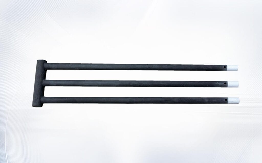
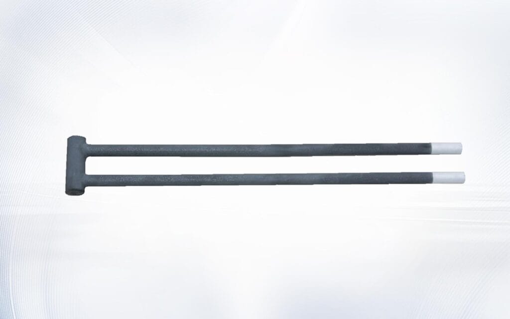
Un elemento en forma de U puede llevar dos patas terminales hacia el mismo lado de un horno porque las varillas están conectadas por un puente. Un elemento en forma de W puede utilizar varias patas paralelas conectadas en el otro extremo. Estas disposiciones proporcionan acceso a terminales del mismo lado, pero no deben describirse automáticamente como eléctrica o estructuralmente idénticas a un elemento recto de un solo extremo tipo UX.
El Varilla de carburo de silicio en forma de U requiere mediciones como el espaciado entre las patas, las dimensiones del puente, la longitud de calentamiento, la longitud del extremo frío y la profundidad de inserción.
A Varilla de carburo de silicio en forma de W requiere confirmación adicional de la cantidad de patas, el espaciado adyacente, las secciones de conexión, el diseño de los terminales y la forma en que se distribuye la energía a través de la geometría completa.
Al evaluar el acceso del mismo lado, separe estas preguntas:
- ¿Dónde están los terminales externos?
- ¿cuántas aberturas para hornos se requieren?
- ¿Cómo viaja la corriente a través del elemento?
- ¿Qué secciones forman la zona de calentamiento activo?
- ¿cómo se soporta mecánicamente el elemento?
- ¿Cómo puede expandirse?
- ¿En qué dirección se retira?
- ¿Qué dimensiones definen el puente de conexión o camino de retorno?
Esto evita que una disposición de terminal conveniente se confunda con una especificación técnica completa.
La expansión térmica debe permanecer libre
Todos los componentes del horno de alta temperatura se mueven a medida que cambia la temperatura. El revestimiento del horno, la carcasa de acero, los soportes, los manguitos, el hardware de conexión y elementos calefactores de carburo de silicio no necesariamente expandirse en la misma cantidad o en la misma dirección.
Elementos rectos de doble extremo
Un elemento recto que pase a través de paredes opuestas no debe sujetarse rígidamente en ambos extremos. Si ambas paredes restringen su movimiento, la expansión térmica puede crear tensiones de flexión o compresión.
Las correas terminales deben transportar corriente sin tirar del elemento hacia los lados. Los soportes deben mantener la posición aprobada y al mismo tiempo permitir el movimiento requerido.
Elementos de un solo extremo
Se inserta un elemento de un solo extremo desde un lado, pero la sección caliente interna aún requiere un espacio adecuado. El extremo sellado o sin soporte no debe golpear el revestimiento de la cámara, la carga del proceso u otro elemento a medida que el horno se calienta.
La disposición de montaje no debe tratar el conjunto terminal como un anclaje estructural rígido a menos que esa función esté incluida específicamente en el diseño aprobado.
Elementos moldeados
En forma de U y W elementos calefactores de carburo de silicio introduzca múltiples patas y secciones de conexión. Alturas de soporte desiguales, espaciado central incorrecto o alineación forzada pueden cargar los puentes.
Por lo tanto, un dibujo dimensional debería identificar puntos de referencia tanto eléctricos como mecánicos. La distancia entre las patas terminales no es simplemente una medida de instalación conveniente; determina si el elemento conformado encaja sin tensión.
La ubicación en la zona caliente es más importante que la longitud total
La longitud total responde sólo a una pregunta: ¿cuánto dura el elemento? No muestra dónde se liberará el calor útil.
Un dibujo completo debe ubicar:
- Longitud de la zona de calentamiento
- Longitud del extremo frío
- Transición de caliente a frío
- Grosor de la pared del horno
- Espesor de aislamiento
- Zona de contacto terminal
- Posición de la cámara
- Liquidación de la carga del proceso
- Puntos de apoyo
- Posición de extremo sellado o puente
Para doble extremo elementos calefactores de carburo de silicio, la zona caliente debe permanecer entre las caras de la pared interior a menos que el diseño del horno aprobado indique lo contrario.
Para un elemento de un solo extremo, la zona caliente puede extenderse desde la sección fría del lado de conexión hacia el extremo sellado. Por lo tanto, el comprador debe verificar tanto la transición cerca de la pared como el espacio libre en el otro extremo.
Si parte de la zona caliente se encuentra dentro del revestimiento, la abertura del horno puede sobrecalentarse. Si la sección activa se coloca demasiado dentro de la cámara, la distribución de temperatura puede alejarse del área de carga prevista.
El tiempo de mantenimiento debe influir en el diseño original
La planificación del mantenimiento a menudo se pospone hasta que se haya instalado el horno. En esa etapa, las cubiertas de terminales, tuberías, protecciones o equipos cercanos pueden impedir el reemplazo eficiente de elementos.
Preguntas para diseños de un solo extremo
- ¿Se puede retirar todo el elemento del lado de conexión?
- ¿La ruta de eliminación es más larga que el elemento completo?
- ¿Pueden los técnicos alcanzar cada abrazadera sin inclinarse sobre una superficie caliente?
- ¿Se pueden quitar las cubiertas de los terminales de forma independiente?
- ¿Hay suficiente espacio para etiquetar y separar conductores emparejados?
- ¿Puede el extremo sellado despejar los soportes internos durante la extracción?
- ¿Los elementos vecinos obstruirán el camino de reemplazo?
Preguntas para diseños de doble extremo
- ¿Se pueden aislar y acceder de forma segura a ambos lados de la terminal?
- ¿Están alineadas las aberturas opuestas?
- ¿En qué dirección se eliminará el elemento?
- ¿Se debe desmontar primero un recinto terminal?
- ¿se pueden aflojar las tiras conductoras sin girar la varilla?
- ¿Se reserva permanentemente suficiente espacio axial?
- ¿Se pueden inspeccionar ambos extremos durante el mantenimiento de rutina?
Antes de cualquier servicio de horno, el equipo debe apagarse, aislarse y enfriarse de acuerdo con los procedimientos de la instalación. La guía sobre control de energías peligrosas explica por qué durante el mantenimiento se debe controlar la energía eléctrica, mecánica, química y térmica.
Patrones de falla que pueden indicar un problema de diseño
No todos los elementos dañados son defectos materiales. Fallas repetidas en la misma ubicación pueden indicar que el diseño seleccionado o el hardware circundante está aplicando tensión.
| Condición observada | Posible causa relacionada con el diseño | Prioridad de inspección |
| Rotura cerca de la pared de un horno | Apertura desalineada, expansión restringida o terminal cargado lateralmente | Alineación de orificios, posición de soporte y tensión del conductor |
| Sobrecalentamiento terminal repetido | Contacto flojo, conector de tamaño insuficiente, exposición al calor o terminales congestionados | Abrazaderas, tiras conductoras, superficies de contacto y colocación de extremos fríos |
| Grieta cerca de un puente perfilado | Espaciado incorrecto de las piernas o soporte desigual | Espaciado central, altura del soporte y espacio libre del puente |
| Daño en el extremo sellado | Liquidación interna insuficiente | Profundidad de inserción y movimiento térmico |
| Un lado del horno se calienta más | Posición de la zona caliente o desequilibrio de zonificación | Posición del elemento, agrupación de resistencia y salida del controlador |
| El elemento de repuesto no se puede quitar | El sobre de servicio no estaba reservado | Ruta de retiro y equipamiento circundante |
| El nuevo elemento falla después de una instalación forzada | La geometría del orificio o manguito no coincide | Dimensiones reales y dibujo aprobado |
| Corriente desigual entre elementos | Resistencia o desajuste del circuito | Lecturas de resistencia individuales y cableado de zona |
Cuando varios elementos calefactores de carburo de silicio si muestra daños similares, cambiar el modelo del elemento sin investigar el horno puede reproducir el mismo fallo.
La guía para Terminales de elementos calefactores de SiC proporciona comprobaciones adicionales de contacto flojo, ajuste de abrazaderas, condición de tira conductora y sobrecalentamiento de terminales.
Elegir un diseño para un nuevo horno
Los nuevos proyectos de hornos brindan la mejor oportunidad para coordinar el elemento, las aberturas de las paredes, el cableado y el acceso al servicio.
Paso 1: Defina el deber de calefacción
Document:
- Temperatura normal de funcionamiento
- Temperatura máxima de funcionamiento
- Ambiente de horno
- Dimensiones de la cámara
- Tamaño de carga del proceso
- Uniformidad de temperatura requerida
- Ciclo de calefacción y refrigeración
- Tensión disponible
- Energía de calefacción instalada
- Número de zonas de control
Una descripción general de material de carburo de silicio puede proporcionar antecedentes útiles, pero los límites operativos reales deben provenir del elemento aprobado y del diseño del horno.
Paso 2: Acceso Permanente al Mapa
Identifique qué lados del horno seguirán siendo accesibles después de que se hayan instalado todos los servicios públicos, plataformas, protectores y equipos de producción.
Si solo una pared es accesible de manera confiable, de un solo extremo elementos calefactores de carburo de silicio o puede merecer prioridad una estructura apropiada con forma de terminal del mismo lado. Si ambas paredes permanecen abiertas, una disposición de doble extremo puede ofrecer una ruta de corriente más simple y una menor densidad de terminales.
Paso 3: seleccione una geometría
Elija entre estructura recta, ranurada en espiral, de un solo extremo, en forma de U, en forma de W u otra estructura diseñada. No seleccione geometría únicamente a partir de declaraciones de temperatura o fotografías de productos.
Paso 4: Coordinar el muro
Defina el diámetro del orificio, las dimensiones del manguito, la separación central, el espesor de la pared, la posición de transición, la proyección del terminal y la holgura de expansión.
Paso 5: Complete la revisión eléctrica
Confirme la resistencia, tolerancia, voltaje, corriente, agrupación, capacidad del controlador, rango del transformador cuando corresponda, tamaño del conductor y equilibrio de fase.
Paso 6: Simular el reemplazo
Utilice las dimensiones completas del elemento para verificar que un técnico pueda retirar e instalar la pieza una vez que el horno esté completamente ensamblado. Esta sencilla revisión puede revelar conflictos que son invisibles en el cálculo del calentamiento.
Modernización de un horno existente
Cambio de doble extremo a único extremo elementos calefactores de carburo de silicio, o en sentido contrario, no es una sustitución directa. Es una modificación del horno.
De doble extremo a simple extremo
Las posibles motivaciones incluyen el acceso trasero bloqueado, el deseo de centralizar el cableado o la necesidad de eliminar los terminales por un lado.
La revisión de modernización debe verificar:
- Si el nuevo elemento puede ofrecer la longitud calentada requerida
- Requisitos de orificio y manguito del lado de conexión
- Espacio libre interno extremo
- Densidad terminal
- Capacidad de cables y gabinetes
- Compatibilidad de resistencia y tensión
- Posición de apoyo
- Sellado de aberturas traseras no utilizadas
- Distribución de temperatura después del cambio de geometría
- Espacio de remoción
Cerrar una abertura no utilizada debería restaurar el rendimiento adecuado del revestimiento, el aislamiento y la carcasa. Es posible que una cubierta externa delgada por sí sola no reproduzca el límite térmico original.
De un solo extremo a dos extremos
Las posibles motivaciones incluyen cambiar a una estructura recta más simple o distribuir las conexiones a través de dos paredes del horno.
Esta conversión puede requerir:
- Una nueva abertura a través de la pared opuesta
- Alineación precisa entre ambos orificios
- Nuevas fundas y protección de terminales externos
- Enrutamiento eléctrico al segundo lado
- Autorización de mantenimiento adicional
- Soportes revisados
- Protección de seguridad actualizada
- Un nuevo procedimiento de eliminación de elementos
Debido a que se deben modificar la carcasa y el revestimiento del horno, el trabajo debe revisarse como un cambio de ingeniería en lugar de una sustitución de compras.
Matriz de Decisión para Compradores Industriales
Utilice esta matriz únicamente como dirección inicial. La selección final requiere datos mecánicos y eléctricos aprobados.
| Condición del horno | Probable dirección inicial | Confirmación crítica |
| Sólo se puede acceder a una pared | Estructura de un solo extremo o del mismo lado | Espacio de retiro y densidad terminal |
| Ambos muros tienen acceso permanente | El doble extremo puede resultar práctico | Alineación de orificios y holgura de extracción axial |
| La pared trasera debe permanecer sellada | Un solo extremo puede reducir las penetraciones | Espacio libre interno sellado |
| El horno existente utiliza terminales opuestos | Mantenga el doble extremo a menos que el rediseño esté justificado | Dimensiones originales y resistencia |
| El elemento existente tiene ambos cables en un extremo | Revise la estructura exacta de un solo extremo | Ruta interna, detalles de la terminal y posición de la zona caliente |
| La cámara grande requiere varias patas paralelas | Revise la geometría en forma de U o W | Espaciado, dimensiones de puentes, soportes y circuito |
| La zona de la terminal ya está abarrotada | Los de doble extremo pueden distribuir conexiones | Acceso y enrutamiento de conductores en ambos lados |
| El horno está instalado cerca de la pared de un edificio | Un solo extremo puede simplificar el servicio | Ruta de eliminación completa en el lado accesible |
| La modernización no tiene un dibujo aprobado | No seleccione todavía | Mida el horno y reconstruya la especificación |
| Los elementos nuevos deben ejecutarse con elementos envejecidos | Cualquiera de las dos geometrías requiere revisión eléctrica | Capacidad de control y adaptación de resistencia |
Un buen historial de decisiones explica por qué los seleccionados elementos calefactores de carburo de silicio adaptarse al horno. No debe indicar simplemente que una estructura estuvo disponible antes o parecía similar a la varilla vieja.
Información de RFQ para elementos de una y dos puntas
Una solicitud de cotización completa debe incluir la siguiente información.
| Categoría de solicitud de cotización | Detalles requeridos |
| Disposición de elementos | De un solo extremo, de dos extremos, con la misma forma lateral o por confirmar |
| Geometría del elemento | Recto, ranurado en espiral, en forma de U, en forma de W o personalizado |
| Dimensiones | Diámetro, HZ, CZ, OL, profundidad de inserción y puntos de transición |
| Dimensiones del elemento moldeado | Cantidad de patas, espaciado entre centros, tamaño del puente y disposición de terminales |
| Resistencia | Valor requerido, tolerancia y condición de referencia |
| Datos eléctricos | Agrupación de voltaje, corriente, potencia instalada, circuito, controlador y zona |
| Muro del horno | Diámetro del orificio, espesor del revestimiento, manguito, sello y espacio libre disponible |
| Cámara | Dimensiones internas, posición del elemento y distancia de la carga del proceso |
| Condiciones de funcionamiento | Temperatura de trabajo, temperatura máxima, atmósfera y ciclo |
| Montaje | Posición horizontal o vertical, soportes y margen de expansión |
| Conexiones | Tipo de abrazadera, tamaño de tira conductora, dirección del cable y dimensiones de la cubierta |
| Mantenimiento | Lados accesibles, dirección de extracción y distancia de extracción disponible |
| Equipo existente | Dibujos, fotografías, registros de resistencia e historial de fallas |
| Requisito de pedido | Cantidad instalada, cantidad de zona y cantidad de repuesto requerida |
Las fotografías deben mostrar el lado completo del horno, no solo un primer plano de la varilla vieja. Incluya una escala y etiquete cada posición fotografiada por zona del horno.
La consulta también debe indicar si el proyecto implica un reemplazo directo, una modernización del horno o un diseño completamente nuevo. Esto impide que un proveedor asuma que las aberturas y los datos eléctricos existentes permanecerán sin cambios.
Inspección entrante antes de la instalación
Entregado elementos calefactores de carburo de silicio debe comprobarse antes del cierre previsto del horno.
Verificar:
- Estructura y disposición de terminales
- Diámetro
- Longitud de la zona caliente
- Longitud del extremo frío
- Longitud total
- Profundidad de inserción
- Dimensiones del extremo sellado o del puente
- Espaciado de las piernas cuando corresponda
- Etiqueta de resistencia y agrupación
- Zona de contacto terminal
- Rectitud y daño visible
- Compatibilidad con abrazaderas y tiras conductoras
- Identificación de cantidad y zona del horno
- Condición de embalaje
Registre los valores reales en lugar de escribir sólo “aprobado”.” Si una dimensión difiere del dibujo aprobado, resuélvalo antes de intentar la instalación.
No se debe aceptar un elemento físicamente similar simplemente porque pasa a través del orificio del horno. La posición del terminal, la ubicación de la zona activa, la resistencia y la compatibilidad del circuito siguen siendo parte de la inspección.
Preguntas frecuentes
¿Son más eficientes los elementos calefactores de carburo de silicio de un solo extremo?
No automáticamente. La posición de la conexión por sí sola no determina la eficiencia del sistema. El rendimiento depende de la resistencia del elemento, la carga superficial, la ubicación de la zona caliente, el aislamiento del horno, los controles, las pérdidas de calor, la atmósfera y la operación del proceso.
¿Cuándo debo utilizar un elemento de un solo extremo?
Un diseño de un solo extremo es útil cuando solo se puede acceder a una pared del horno, la pared opuesta debe permanecer libre de terminales o el cableado debe estar centralizado. El horno aún debe proporcionar una profundidad de inserción, espacio libre para los terminales y espacio de extracción adecuados.
¿Cuándo es más práctico un elemento de doble extremo?
Un diseño de doble extremo puede resultar práctico cuando ambos lados del horno son permanentemente accesibles y ya existen aberturas alineadas. Puede distribuir hardware terminal a través de dos paredes y proporcionar una ruta de corriente sencilla de extremo a extremo.
¿Puede un elemento de un solo extremo reemplazar una varilla de dos extremos?
No como una sustitución directa. La ubicación de la zona caliente, las aberturas de las paredes, los soportes, la resistencia, el cableado, la densidad de los terminales, el sellado y la ruta de extracción deben rediseñarse y aprobarse.
¿Los elementos en forma de U cuentan como elementos de un solo extremo?
Pueden proporcionar terminales en el mismo lado, pero su geometría y trayectoria eléctrica difieren de una estructura recta de un solo extremo. Especifíquelos como elementos en forma de U e incluya el espaciado entre las patas, las dimensiones del puente, la profundidad de inserción y la disposición de los terminales.
¿por qué es importante la autorización de remoción?
Un técnico debe poder retirar todo el elemento sin golpear el equipo circundante ni doblar la varilla. El acceso al terminal por sí solo no garantiza que sea posible reemplazarlo.
¿Puedo elegir elementos calefactores de carburo de silicio únicamente a partir de la temperatura del horno?
No. La temperatura es sólo un factor de selección. Los compradores también deben proporcionar atmósfera, dimensiones, voltaje, resistencia, potencia, disposición del circuito, dirección de montaje, acceso y ciclo operativo.
¿Qué causa que los elementos se rompan cerca de la pared del horno?
Las posibles causas incluyen agujeros desalineados, expansión restringida, instalación forzada, conductores con carga lateral, colocación incorrecta de la zona caliente o impacto mecánico. Se debe inspeccionar la instalación completa antes de culpar únicamente al elemento.
¿deberían fijarse firmemente ambos extremos de un elemento recto?
Un elemento frágil de alta temperatura no debe sujetarse rígidamente de manera que impida el movimiento térmico. Los soportes y conexiones aprobados deben sujetar el elemento correctamente y al mismo tiempo acomodar la expansión.
¿Qué debo enviar para una revisión técnica?
Envíe un dibujo dimensionado, fotografías del horno, mapa del lado accesible, temperatura de funcionamiento, atmósfera, voltaje, potencia, resistencia, disposición del circuito, espesor de pared, dimensiones del orificio, detalles de la terminal, cantidad requerida e historial de reemplazo a través del página de contacto.
Conclusión
Elegir entre de un solo extremo y de dos extremos elementos calefactores de carburo de silicio comienza con la disposición del horno, no con el nombre del producto. La ubicación del terminal afecta las paredes que requieren aberturas, el recorrido de los conductores eléctricos, la densidad del hardware de conexión, el espacio necesario para el mantenimiento y la dirección en la que se puede eliminar un elemento.
Las estructuras de un solo extremo pueden resolver problemas de acceso genuinos cuando solo hay disponible un lado del horno. Las estructuras de doble extremo pueden proporcionar una disposición sencilla cuando ambas paredes permanecen accesibles. Los elementos en forma de U y W pueden llevar terminales hacia el mismo lado, pero requieren dibujos específicos de geometría y no deben tratarse como idénticos a los elementos rectos de un solo extremo.
El proceso de selección más confiable combina geometría de elementos, posición de la zona caliente, resistencia, diseño de circuitos, construcción de paredes, espacio libre de expansión, atmósfera operativa y acceso de mantenimiento permanente. Cuando esos factores se documentan juntos, elementos calefactores de carburo de silicio pase a formar parte de un sistema de horno diseñado en lugar de un componente de reemplazo aislado.