Cuando un horno industrial comienza a calentarse lentamente, desarrolla zonas frías o requiere ajustes frecuentes de energía, el elemento calefactor visible no siempre es el problema completo. Uno de los valores diagnósticos más importantes es la resistencia del elemento calefactor de carburo de silicio.
La resistencia determina cómo se distribuye la energía eléctrica a través de un elemento calefactor. Afecta la producción de calor, el equilibrio del horno, la recuperación de temperatura, el rendimiento del controlador y la forma en que varios elementos operan juntos en la misma zona de calentamiento.
A medida que los elementos de carburo de silicio funcionan a altas temperaturas, sus características eléctricas cambian gradualmente. Esta es una parte normal del envejecimiento de los elementos. Sin embargo, cuando se ignoran los cambios de resistencia, un horno previamente estable puede comenzar a producir temperaturas desiguales, ciclos de calentamiento más largos, terminales sobrecalentados o resultados de procesamiento inconsistentes.
Comprender la resistencia de los elementos calefactores de carburo de silicio facilita la identificación correcta de los elementos envejecidos, agrupar las varillas de reemplazo, mantener zonas equilibradas del horno y evitar reemplazar el componente incorrecto.
Qixiang suministra varios tipos de elementos calefactores de carburo de silicio para hornos industriales, hornos cerámicos, hornos de laboratorio, equipos de calefacción de vidrio y otras aplicaciones de alta temperatura.
Tabla de contenidos
¿qué es la resistencia de los elementos calefactores de carburo de silicio?
La resistencia eléctrica describe con qué fuerza un componente se opone al flujo de corriente eléctrica. En un elemento calefactor de carburo de silicio, esta resistencia convierte la energía eléctrica en calor.
La relación básica entre voltaje, corriente y resistencia se describe mediante La ley de Ohm. Aunque los sistemas de calefacción de hornos son más complejos que un simple circuito, el principio sigue siendo útil: los cambios en la resistencia de los elementos afectan el flujo de corriente y la potencia de calentamiento.
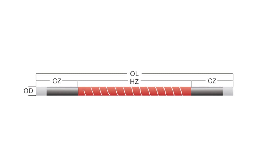
Un elemento calefactor de carburo de silicio normalmente consta de:
- Una zona de calefacción activa
- Uno o más extremos fríos de baja temperatura
- Zonas de conexión eléctrica
- Correas conductoras o accesorios terminales
- Soportes para hornos o orificios de montaje
La sección activa está diseñada para generar la mayor parte del calor. Los extremos fríos permiten la conexión eléctrica al tiempo que limitan el calentamiento innecesario cerca de la pared del horno y el área del terminal.
Si la resistencia del elemento no coincide con el diseño eléctrico del horno, el elemento puede producir muy poco calor, consumir corriente inadecuada o crear un desequilibrio cuando se conecta con otros elementos.
Por qué cambia la resistencia durante el funcionamiento del horno
El carburo de silicio es un material semiconductor de alta temperatura. Su comportamiento eléctrico está influenciado por la composición del material, la microestructura, los aditivos, la porosidad, la temperatura y las condiciones de fabricación.
Investigación sobre el resistividad eléctrica de cerámicas de carburo de silicio muestra que la resistividad del SiC puede verse afectada por factores como la porosidad, la estructura cristalina, los aditivos y las condiciones de procesamiento.
En un elemento calefactor de horno, el funcionamiento a largo plazo también cambia la superficie del elemento y la estructura interna. Las influencias comunes incluyen:
- Oxidación a alta temperatura
- Calentamiento y enfriamiento repetidos
- Ambiente de horno
- Procesar vapor y contaminación
- Carga eléctrica
- Sobrecalentamiento local
- Estrés mecánico
- Envejecimiento superficial
A medida que estos cambios se acumulan, la resistencia operativa del elemento generalmente aumenta. El controlador del horno puede compensar suministrando más voltaje o ajustando la salida de potencia, pero el rango de compensación disponible no es ilimitado.
Con el tiempo, el horno puede tener dificultades para alcanzar su temperatura objetivo aunque el elemento calefactor todavía esté físicamente intacto.
El envejecimiento por resistencia no es lo mismo que el fracaso del elemento
No es necesario romper completamente un elemento calefactor de carburo de silicio antes de que afecte el rendimiento del horno.
Un elemento puede parecer normal durante la inspección visual mientras su resistencia ya ha cambiado significativamente. Esto puede resultar en:
- Calentamiento más lento del horno
- Reducción de la producción de calor en una zona
- Aumento de la demanda de energía
- Recuperación desigual de temperatura
- Diferentes velocidades de calentamiento entre elementos
- Ajuste más frecuente del controlador
- Mala repetibilidad del proceso
Esta es la razón por la que la medición de la resistencia es más útil que la inspección visual por sí sola.
Un elemento agrietado o roto es fácil de identificar. Un elemento envejecido eléctricamente puede continuar funcionando mientras reduce gradualmente la estabilidad de producción.
La guía de Qixiang para varillas de carburo de silicio para hornos explica cómo la disposición de los elementos, la carga del horno, la agrupación de resistencias y las prácticas de mantenimiento trabajan juntas para influir en el rendimiento del horno.
Por qué es importante la coincidencia de resistencia en hornos multielementos
Los hornos industriales suelen utilizar varios elementos calefactores de carburo de silicio en una zona eléctrica. Estos elementos deben funcionar juntos como un grupo equilibrado.
Si los valores de resistencia son similares, la energía eléctrica se puede distribuir de manera más uniforme. Si un elemento tiene una resistencia mucho mayor o menor que los demás, el rendimiento de calentamiento puede volverse inestable.
Posibles resultados incluyen:
- Un elemento que calienta con más fuerza que otro
- Temperaturas desiguales de las paredes del horno
- Mayor estrés sobre ciertos elementos
- Diferentes tasas de envejecimiento dentro de una misma zona
- Dificultad del controlador para mantener una temperatura uniforme
- Puntos calientes locales o zonas frías
- Fallo prematuro de elementos recién instalados
Este problema aparece a menudo cuando un único elemento fallido se reemplaza por uno nuevo mientras los elementos restantes ya han funcionado durante mucho tiempo.
El nuevo elemento y los elementos envejecidos pueden tener valores de resistencia significativamente diferentes. Aunque el elemento de reemplazo tenga el tamaño y la forma correctos, es posible que la zona ya no funcione de manera uniforme.
¿debería reemplazarse un elemento o toda la zona?
No existe una regla universal según la cual cada elemento de un horno debe reemplazarse siempre juntos. La decisión correcta depende de las mediciones de resistencia, la antigüedad del elemento, el diseño del horno y los requisitos de producción.
Reemplazar un elemento puede ser razonable cuando:
- Los elementos restantes tienen valores de resistencia similares
- Los demás elementos son todavía relativamente nuevos
- El elemento averiado resultó dañado mecánicamente
- La variación de resistencia permanece dentro del rango de agrupación aceptable
- La zona del horno se puede equilibrar después del reemplazo
Reemplazar varios elementos o una zona completa puede ser más adecuado cuando:
- Los elementos existentes han funcionado durante mucho tiempo
- Los valores de resistencia difieren significativamente
- Varios elementos muestran signos de envejecimiento
- La uniformidad de la temperatura ya se ha deteriorado
- El controlador está cerca de su rango máximo de compensación
- La coherencia de la producción es fundamental
El objetivo no es simplemente sustituir el elemento roto. El objetivo es restablecer el calentamiento equilibrado del horno.
Cómo medir la resistencia de los elementos calefactores de carburo de silicio
Las mediciones de resistencia deben realizarse utilizando equipos de medición eléctricos adecuados y procedimientos de seguridad establecidos de la planta.
El horno debe estar aislado de energía eléctrica antes de la inspección. Las mediciones sólo deben ser realizadas por personal capacitado que comprenda el circuito del horno y los peligros eléctricos.
Un proceso de medición práctico incluye los siguientes pasos.
Aislar el horno
Apague y aísle la fuente de alimentación del horno. Confirme que el circuito eléctrico no pueda energizarse accidentalmente durante la inspección.
Deje que el horno se enfríe
Las lecturas de resistencia pueden verse influenciadas por la temperatura. Las mediciones utilizadas para la comparación deben tomarse en condiciones consistentes.
No compare un elemento medido en caliente con otro elemento medido a temperatura ambiente.
Desconecte el elemento cuando sea necesario
Dependiendo del circuito del horno, medir un elemento mientras permanece conectado puede incluir resistencia de otros elementos o componentes eléctricos.
Desconectar el elemento del circuito puede proporcionar una lectura individual más confiable.
Inspeccionar las conexiones
Antes de medir, verifique si las correas conductoras, terminales, abrazaderas o superficies de contacto están sueltas, oxidadas o contaminadas.
Un mal contacto eléctrico puede crear lecturas engañosas y sobrecalentamiento local.
Mida cada elemento
Registre el valor de resistencia de cada elemento en la zona de calentamiento. No mida sólo el elemento que parece dañado.
Comparar los resultados
Compare elementos dentro de la misma zona y revise registros de mantenimiento anteriores cuando estén disponibles.
Una única lectura de resistencia tiene un significado limitado sin un punto de referencia. Las comparaciones más útiles son:
- Valor actual versus valor original
- Valor actual versus valor de mantenimiento anterior
- Un elemento versus otros elementos en la misma zona
- Una zona de horno versus otra zona similar
Tabla de medición de resistencia
| Resultado de la medición | Posible significado | Cheque recomendado |
|---|---|---|
| Resistencia similar en una zona | Los elementos están equilibrados eléctricamente | Continuar con el monitoreo de rutina |
| Un elemento tiene una resistencia mucho mayor | Envejecimiento avanzado o mala conexión | Inspeccionar elementos y terminales |
| Un elemento tiene una resistencia inusualmente baja | Elemento incorrecto, problema de medición o variación del material | Vuelva a verificar las medidas y especificaciones |
| La resistencia cambia rápidamente entre inspecciones | Envejecimiento acelerado o condiciones anormales del horno | Verifique la atmósfera, la carga y la configuración eléctrica |
| Todos los elementos muestran una resistencia gradualmente mayor | El envejecimiento normal de la zona puede estar progresando | Revisar el rango de compensación del controlador |
| La resistencia parece inestable | Conexión floja o mal contacto con el medidor | Inspeccione correas, abrazaderas y terminales |
| Los elementos nuevos y antiguos difieren significativamente | No coincidencia de reemplazo | Reagrupar o sustituir elementos por zona |
| La resistencia es aceptable pero el calentamiento sigue siendo desigual | El problema puede ser la carga, el aislamiento, la posición del sensor o los controles | Inspeccione todo el sistema del horno |
La resistencia al frío y la resistencia operativa son diferentes
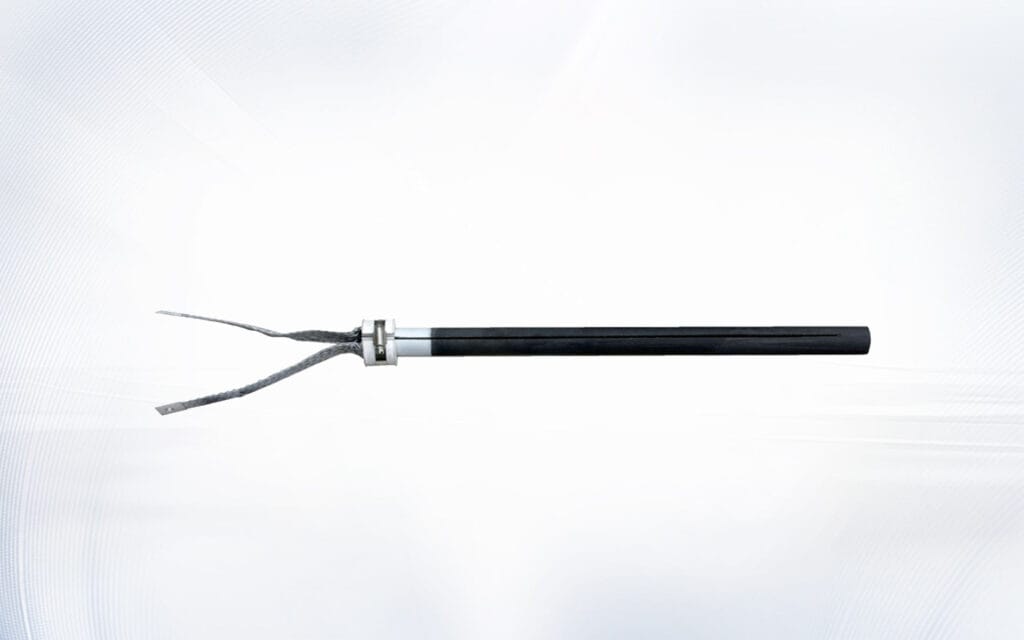
Una lectura de resistencia tomada cuando el elemento está frío no debe tratarse como idéntica a la resistencia durante el funcionamiento a alta temperatura.
El carburo de silicio tiene un comportamiento eléctrico dependiente de la temperatura. La relación real depende de la composición del elemento, la estructura, la temperatura de funcionamiento y el proceso de fabricación.
Para fines de mantenimiento, la coherencia es esencial. Las lecturas de resistencia deben ser:
- Tomado a temperaturas similares
- Medido utilizando el mismo método
- Grabado con el mismo tipo de instrumento
- Comparado con las especificaciones del proveedor
- Evaluado dentro de la misma zona del horno
Esto hace que el análisis de tendencias sea mucho más confiable.
El propósito de la medición rutinaria no es sólo obtener un número exacto. Es observar cómo cambia el elemento con el tiempo.
Cómo afecta la resistencia a la potencia del horno
La resistencia, el voltaje, la corriente y la potencia están interconectados. Un cambio en un valor afecta a los demás.
En un sistema de horno con una configuración eléctrica fija, aumentar la resistencia del elemento puede reducir la corriente y alterar la producción de calor. Es posible que el controlador o transformador deba compensar ajustando el voltaje disponible.
Si la resistencia continúa aumentando, el horno puede llegar a un punto en el que el sistema eléctrico no pueda proporcionar una compensación suficiente.
Las señales de advertencia típicas incluyen:
- Ciclos de calentamiento más largos
- Recuperación más lenta después de que se abre la puerta del horno
- Dificultad para alcanzar la temperatura máxima
- Mayor diferencia de temperatura entre zonas
- Controles de potencia que operan cerca de su límite
- Mayor uso de energía por ciclo de producción
- Ajuste frecuente de tomas de transformador
El rendimiento del calentamiento del proceso industrial depende del sistema completo, incluidos los elementos calefactores, los controles, el aislamiento, la carga y las prácticas operativas. La orientación del Departamento de Energía de EE. UU. sobre sistemas de calefacción de procesos industriales destaca también el valor de evaluar los equipos de calefacción como un sistema integrado.
Problemas de resistencia causados por conexiones terminales
No todas las lecturas de resistencia anormales significan que el elemento de carburo de silicio esté dañado.
Los problemas de conexión pueden aumentar la resistencia de contacto en el área terminal. Esta resistencia de contacto genera calor donde no se desea calor.
Los problemas de conexión comunes incluyen:
- Correas conductoras sueltas
- Superficies terminales oxidadas
- Presión de sujeción incorrecta
- Conectores trenzados dañados
- Cold-uri contaminate
- Accesorios desalineados
- Hardware de terminal desgastado
Los signos de resistencia relacionada con la conexión incluyen:
- Decoloración cerca de las terminales
- Sobrecalentamiento localizado fuera de la cámara del horno
- Correas conductoras derretidas o dañadas
- Lecturas de medidores inestables
- Diferentes temperaturas en conexiones similares
- Aflojamiento frecuente después de ciclos térmicos
Al reemplazar elementos, inspeccione los accesorios al mismo tiempo. Suministros Qixiang accesorios para elementos calefactores para conexión eléctrica e instalación mecánica.
Un seleccionado correctamente abrazadera de varilla calefactora puede ayudar a mantener un soporte estable y al mismo tiempo permitir que el sistema se adapte a los ciclos de calefacción y refrigeración.
Cómo influye la atmósfera del horno en el envejecimiento por resistencia
La atmósfera dentro del horno puede influir fuertemente en el estado del elemento calefactor.
Los elementos de carburo de silicio se utilizan comúnmente en atmósferas de aire a alta temperatura, pero los hornos industriales reales pueden contener mucho más que aire limpio.
Influențe potenciale include:
- vapor de agua
- Gases reductores
- Vapor alcalino
- Vapor metálico
- Compuestos de esmalte cerámico
- Emisiones de procesamiento de vidrio
- Depósitos de carbono
- Polvo y polvo
- Gases protectores
- Procesar productos químicos
Estas sustancias pueden reaccionar o depositarse en la superficie del elemento. La contaminación de la superficie puede producir un calentamiento desigual, deterioro local o cambios acelerados de resistencia.
Cuando la resistencia aumente más rápidamente de lo esperado, considere si el proceso de producción ha cambiado.
Las preguntas a investigar incluyen:
- ¿Se ha introducido una nueva materia prima?
- ¿Ha cambiado la atmósfera de disparo?
- ¿Entra más humedad al horno?
- ¿Ha cambiado el sistema de ventilación?
- ¿Están los productos colocados más cerca de los elementos?
- ¿Se está acumulando polvo de proceso en las varillas?
- ¿Ha aumentado la temperatura de funcionamiento?
- ¿Se están volviendo más frecuentes los ciclos de calentamiento?
La vida útil del elemento siempre debe evaluarse junto con el entorno del horno.
Cómo influye la forma del elemento en la selección de resistencia
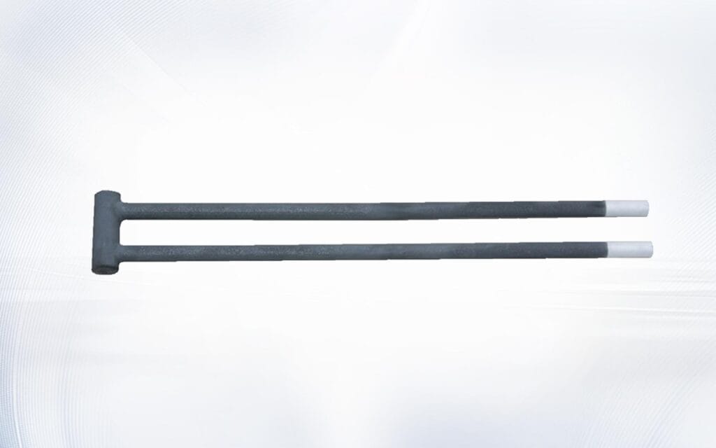
Los elementos calefactores de carburo de silicio están disponibles en diferentes estructuras. La forma del elemento afecta la longitud de calentamiento, el diseño del extremo frío, la conexión eléctrica, el método de instalación y la resistencia total.
Elementos rectos
Los elementos rectos se utilizan frecuentemente en hornos con instalación de pared lateral. El Elemento calefactor SiC tipo DH proporciona una estructura recta de igual diámetro para diseños de hornos adecuados.
Elementos tipo DB
El Elemento de calentamiento de carburo de silicio tipo DB es otra estructura de elementos rectos utilizada para entornos de hornos exigentes. Sus dimensiones y resistencia deben coincidir con el sistema eléctrico del horno.
Elementos de un solo extremo
Los diseños de un solo extremo permiten que ambas conexiones eléctricas permanezcan en un lado del horno. El Varilla de carburo de silicio tipo SGR está destinado a aplicaciones donde se requiere instalación por una sola cara.
Elementos en forma de U y en forma de W
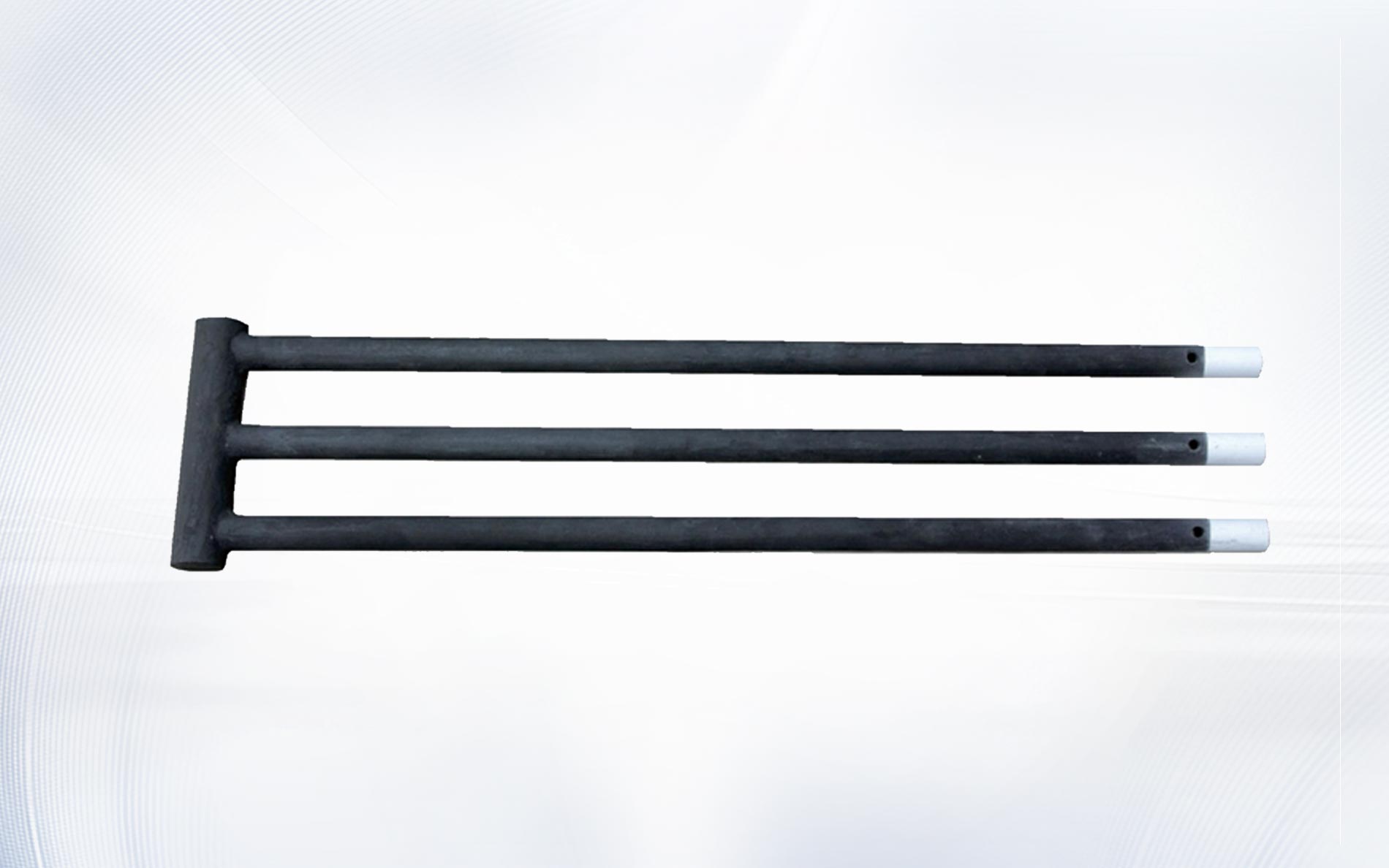
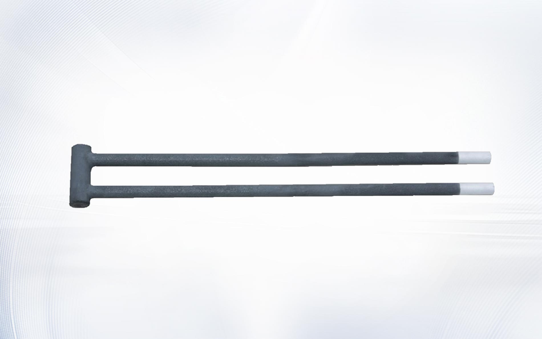
Los elementos en forma de U y W utilizan múltiples patas calefactoras. Su selección de resistencia debe tener en cuenta la geometría del elemento, el espaciado de las patas, la longitud de la zona de calentamiento y el diseño del circuito.
Los tipos de elementos nunca deben cambiarse únicamente porque pasan por la misma abertura del horno. Las especificaciones eléctricas y térmicas también deben coincidir.
Cómo registrar la resistencia para el mantenimiento preventivo
Un programa de monitoreo de resistencia no necesita ser complicado.
Un registro de mantenimiento de horno útil puede incluir:
| Artículo de registro | Información para almacenar |
| Identificación del horno | Número, línea o ubicación del horno |
| Zona de calefacción | Zona izquierda, derecha, superior, inferior o numerada |
| Posición del elemento | Posición exacta dentro del horno |
| Modelo de elementos | DB, DH, SG, SGR, en forma de U, en forma de W u otro tipo |
| Fecha de instalación | Fecha en que el elemento entró en servicio |
| Resistencia original | Proveedor o valor medido inicial |
| Resistencia actual | Valor de cada inspección |
| Temperatura de funcionamiento | Temperatura normal de trabajo del horno |
| Atmósfera | Aire, gas protector, condición reductora o vapor de proceso |
| Condición de conexión | Normal, suelto, oxidado o reemplazado |
| Acción correctiva | Ajuste, reagrupación o sustitución |
Registrar estos detalles permite a los equipos de mantenimiento identificar tendencias en lugar de reaccionar sólo después de una falla.
Por ejemplo, si una posición muestra repetidamente un crecimiento de resistencia más rápido, la causa puede estar relacionada con la colocación de la carga, el flujo de aire, el aislamiento o el enfriamiento del terminal en lugar del elemento en sí.
Errores comunes al evaluar la resistencia
Varios errores pueden hacer que los datos de resistencia no sean confiables.
Medición a diferentes temperaturas
Los valores de resistencia tomados en diferentes condiciones de temperatura no deben compararse directamente.
Medición a través del circuito completo
La lectura puede incluir otros elementos o componentes eléctricos si el elemento permanece conectado.
Ignorar la resistencia del cable del medidor
Para mediciones de resistencia relativamente bajas, los cables de prueba y la calidad del contacto pueden influir en el resultado.
Medición a través de conexiones oxidadas
Los terminales oxidados pueden aumentar el valor medido y ocultar la verdadera resistencia del elemento.
Comparación de diferentes modelos de elementos
Las diferentes formas, diámetros y longitudes de calentamiento tienen naturalmente diferentes especificaciones de resistencia.
Reemplazo solo por apariencia
Un elemento que parece dañado puede no ser el único elemento envejecido eléctricamente en la zona.
Sin registros históricos
Sin mediciones previas, es difícil determinar si la resistencia es estable o aumenta rápidamente.
Solución de problemas de calefacción desigual de hornos
Cuando un horno desarrolla variación de temperatura, se debe verificar la resistencia como parte de un proceso de diagnóstico más amplio.
Comience con la siguiente secuencia:
- Revise el patrón de temperatura dentro del horno.
- Mida la resistencia de los elementos por zona.
- Inspeccione las correas conductoras y los terminales.
- Compruebe si se mezclan elementos antiguos y nuevos.
- Revise la carga del producto y la disposición de los estantes.
- Inspeccione el aislamiento y las aberturas de las paredes del horno.
- Confirme la posición del sensor de temperatura.
- Revise la configuración del controlador y del transformador.
- Compruebe si la atmósfera del proceso ha cambiado.
- Compare el rendimiento actual con registros de mantenimiento anteriores.
Si los valores de resistencia están equilibrados pero la temperatura permanece desigual, el problema puede deberse a radiación de calor bloqueada, aislamiento dañado, ubicación del sensor o carga del horno.
La resistencia es un valor diagnóstico crítico, pero es una parte del sistema de calefacción completo.
Cuando se deben reemplazar los elementos calefactores de carburo de silicio
Se debe considerar el reemplazo cuando el cambio de resistencia comience a afectar el funcionamiento del horno.
Los indicadores de reemplazo comunes incluyen:
- El horno no puede alcanzar la temperatura objetivo
- La compensación del controlador está cerca de su límite
- La resistencia difiere significativamente dentro de una zona
- El tiempo de calentamiento sigue aumentando
- Los elementos muestran grietas o daños superficiales graves
- El sobrecalentamiento del terminal regresa después de la reparación de la conexión
- La calidad del producto se ve afectada por la variación de temperatura
- Varios elementos de una misma zona están muy envejecidos
- Las interrupciones del mantenimiento son cada vez más frecuentes
El reemplazo planificado suele ser más efectivo que esperar a que falle completamente el elemento.
Un reemplazo programado permite al equipo de mantenimiento:
- Agrupar elementos por resistencia compatible
- Inspeccione los orificios del horno y el aislamiento
- Reemplace los accesorios desgastados
- Limpiar las zonas terminales
- Registre los valores de resistencia iniciales
- Verifique el saldo de la zona antes de que se reanude la producción
¿qué información se necesita para la selección de reemplazo?
El reemplazo preciso requiere más que una fotografía de elemento.
Prepare la siguiente información antes de solicitar una recomendación:
- Aplicación de horno
- Temperatura de trabajo
- Temperatura máxima
- Ambiente de horno
- Estructura elemental
- Longitud total
- Longitud de la zona de calentamiento
- Longitud del extremo frío
- Diámetro del elemento
- Espaciado de piernas para elementos conformados
- Resistencia original
- Resistencia actual
- Tensión del horno
- Energía del horno
- Método de conexión del circuito
- Número de elementos por zona
- Problema operativo actual
Qixiang está completo gama de productos incluye elementos calefactores de carburo de silicio rectos, conformados y de un solo extremo para diferentes estructuras de hornos.
Los parámetros técnicos y los detalles operativos del horno se pueden enviar a través del Contacte con nosotros página para selección de elementos y soporte de reemplazo.
Creando una mejor estrategia de emparejamiento de resistencia
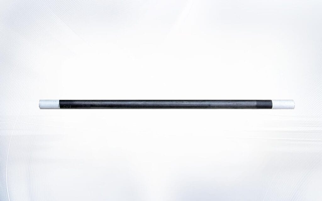
Una estrategia práctica de coincidencia de resistencias debe comenzar antes de instalar los elementos.
Primero, etiquete cada elemento y registre su valor de resistencia suministrado.
En segundo lugar, divida los elementos en grupos con valores similares según el circuito del horno y las recomendaciones del proveedor.
En tercer lugar, instale grupos coincidentes dentro de la misma zona de control.
Cuarto, registra la posición exacta de cada elemento.
Quinto, medir y documentar la resistencia durante el mantenimiento planificado.
Sexto, revisar las diferencias de resistencia antes de reemplazar solo un elemento.
Este proceso reduce la incertidumbre y hace que la resolución de problemas futuros sea mucho más rápida.
También ayuda a identificar si un problema de horno sigue a un elemento específico, una posición de instalación particular o una zona eléctrica completa.
Conclusión
La resistencia de los elementos calefactores de carburo de silicio es uno de los indicadores más útiles del estado del horno. Influye en la carga eléctrica, la producción de calor, la uniformidad de la temperatura, la compensación del controlador y la planificación del reemplazo.
La resistencia normalmente cambia a medida que envejecen los elementos de carburo de silicio. El problema comienza cuando estos cambios no se miden, registran ni comparan en toda la zona del horno.
El mantenimiento confiable del horno debe incluir una medición consistente de la resistencia, inspección de terminales, agrupación de elementos, evaluación de la atmósfera y mantenimiento de registros históricos.
Cuando los valores de resistencia se gestionan adecuadamente, los operadores pueden identificar el envejecimiento antes, evitar reemplazos no coincidentes, reducir el calentamiento desigual y planificar el mantenimiento antes de que se interrumpa la producción.
La mejor decisión de sustitución no se basa únicamente en si un elemento está visiblemente roto. Se basa en cómo funciona eléctrica y térmicamente toda la zona de calentamiento.
Preguntas frecuentes
¿qué causa que aumente la resistencia de los elementos calefactores de carburo de silicio?
La resistencia generalmente aumenta debido al funcionamiento a alta temperatura a largo plazo, la oxidación, el envejecimiento del material, la atmósfera del horno, la contaminación, los ciclos térmicos y el sobrecalentamiento local.
¿Deberían los elementos calefactores de carburo de silicio tener una resistencia idéntica?
Los elementos en la misma zona del horno deben tener valores de resistencia adecuadamente coincidentes. Los requisitos de coincidencia exacta dependen del circuito del horno, el tipo de elemento y las especificaciones del proveedor.
¿Se puede medir la resistencia mientras el elemento aún está instalado?
Puede que sea posible, pero el horno debe estar aislado eléctricamente. Se debe revisar la configuración del circuito porque los componentes conectados pueden afectar la lectura.
¿Se puede instalar un elemento nuevo con elementos más antiguos?
Puede ser posible cuando los valores de resistencia siguen siendo compatibles. Las grandes diferencias entre elementos nuevos y antiguos pueden provocar una distribución desigual de la energía.
¿Por qué el horno se calienta lentamente aunque ningún elemento esté roto?
Los elementos pueden haber envejecido eléctricamente y desarrollado una mayor resistencia. Otras posibles causas incluyen contacto deficiente con el terminal, aislamiento dañado, límites del controlador o radiación de calor bloqueada.
¿Con qué frecuencia se debe medir la resistencia?
El intervalo depende de la temperatura del horno, el cronograma de producción, la atmósfera y la importancia del proceso. Las mediciones deben incluirse en el mantenimiento preventivo regular y registrarse de manera consistente.
¿La atmósfera del horno afecta la resistencia de los elementos?
Sí. El vapor, los gases, el polvo, la humedad y la contaminación del proceso pueden influir en el estado de la superficie del elemento y en la tasa de envejecimiento.
¿Dónde puedo obtener ayuda para igualar la resistencia de reemplazo?
Revisa Qixiang elementos calefactores de carburo de silicio o envíe las dimensiones del horno, los valores de resistencia y las condiciones operativas a través del Contacte con nosotros página.