When a furnace passes its empty-chamber test but produces inconsistent parts, the heater rating is not always the problem. The chamber may be delivering too much power near the door, too little near a heavy fixture, or measuring temperature at a point that does not represent the load. Effective furnace heating zone design starts with the process and its heat-loss pattern, not with dividing the chamber into equal lengths.
This guide explains how to structure furnace heating zone design with silicon carbide elements for batch and continuous equipment. It gives engineers and technical buyers a practical framework for defining zones, placing elements and sensors, specifying electrical capacity, and proving the result under production conditions.
Define the process result before drawing zones
A temperature setpoint is not a complete acceptance criterion. Start furnace heating zone design by documenting the material, load dimensions, load mass, fixture, loading pattern, target temperature, permitted variation, heating rate, soak time, atmosphere, door cycle, and throughput. The U.S. Department of Energy’s process heat overview describes process heating as transferring energy to materials to produce, treat, or alter goods; that load-centered view is essential here.
- Which part temperature actually determines product quality?
- Where are the slowest and fastest locations in the load?
- Does the load enter cold, preheated, or at varying temperatures?
- Does a door, pusher, belt, exhaust, or atmosphere flow disturb one region?
- Which operating case creates the highest duty?
Without those answers, furnace heating zone design can optimize an empty chamber while missing the real manufacturing constraint.
Map heat losses instead of using equal geometric sections
Heat leaves through walls, roof, hearth, penetrations, doors, exhaust, product removal, and moving hardware. The losses are rarely uniform. A sound furnace heating zone design estimates each loss by location and separates steady losses from transient demands such as opening a door or introducing a cold charge.
Draw a longitudinal and cross-sectional heat map. Mark doors, corners, supports, viewports, seals, atmosphere inlets, thermocouples, and areas with different insulation thickness. DOE’s process heating systems resources encourage a systems approach to performance; for furnace heating zone design, that means accounting for enclosure, controls, load, and heat source together.
| Observed pattern | Possible zone-related cause | Evidence to collect |
|---|---|---|
| Cold parts near the door | Door-end loss exceeds local power or recovery capacity | Door-open time, local temperature recovery, element output |
| Hot corners with a cooler centre | Radiant view and element spacing favour the perimeter | Empty and loaded surveys, fixture shielding |
| Cold lower load | Hearth loss or element elevation is not addressed | Top-to-bottom survey and hearth condition |
| Temperature changes with load size | Control sensor does not represent thermal mass | Load profile, sensor response, controller output |
| One zone always at full output | Duty, sensor, wiring, loss, or element capacity mismatch | Zone current, voltage, resistance, and calibrated temperature |
Set zone boundaries where the thermal problem changes
Place a boundary where load condition, heat loss, atmosphere flow, or required temperature control changes materially. In a continuous furnace, preheat, main heat, soak, and exit regions often have different jobs. In a batch furnace, the door, centre, rear wall, roof, and hearth may justify different furnace heating zone design choices even when the chamber is short.
More zones do not automatically create better uniformity. Each additional zone adds sensors, power control, wiring, tuning, failure modes, and commissioning work. The best furnace heating zone design uses enough independently controlled regions to address real gradients while keeping interaction between adjacent zones understandable.
Document what every zone is supposed to correct. “Zone 1 offsets door loss” is actionable; “Zone 1 covers the first metre” is merely geometric. This purpose statement will later guide tuning and troubleshooting.
Match element shape to the available radiating surfaces
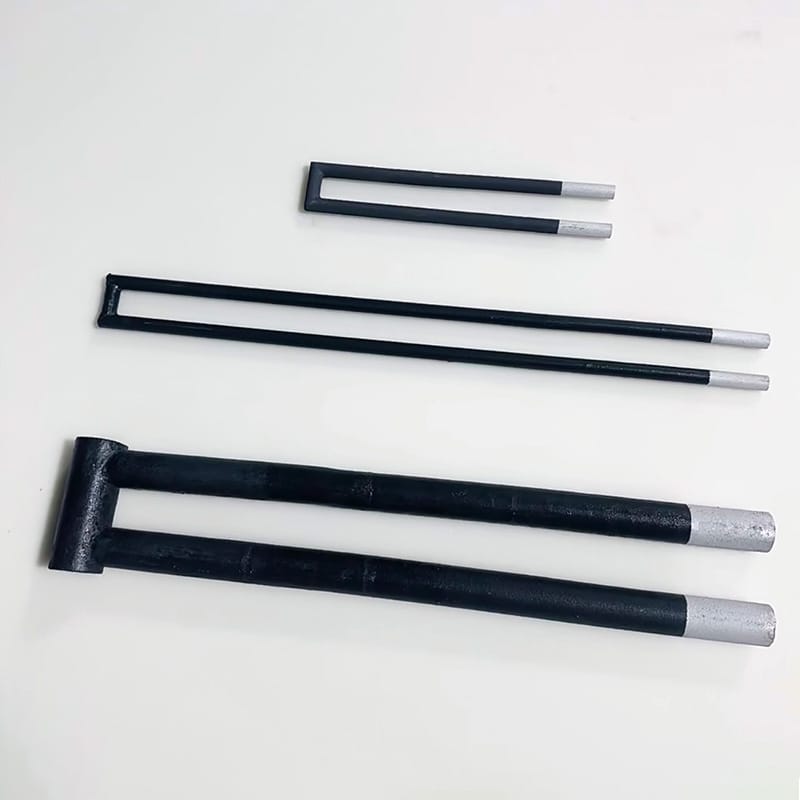
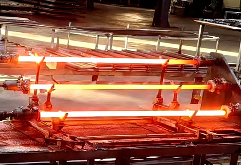
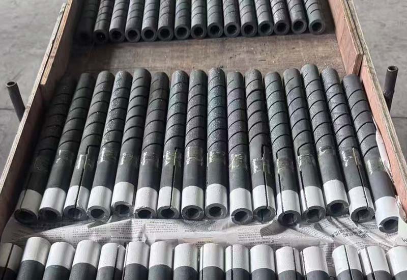
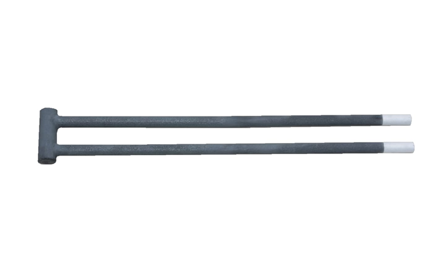
Once zone duty is known, choose element geometry and mounting positions that distribute radiation to the useful load space. Straight elements can serve opposite walls, while multi-leg forms may place a hot section inside the chamber with terminals on one side. Furnace heating zone design must coordinate element shape with wall openings, cold ends, electrical grouping, replacement access, and the load’s line of sight.
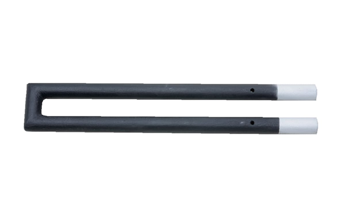
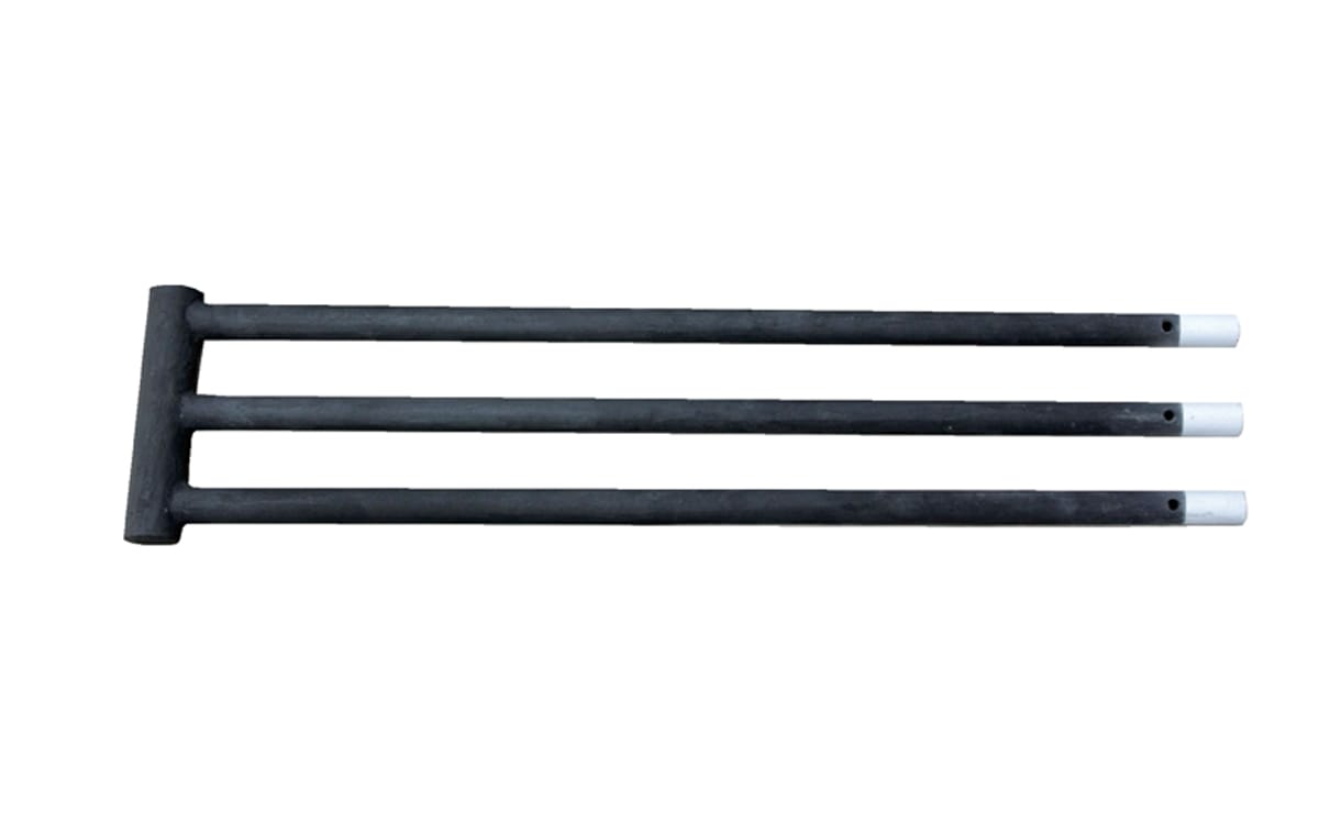
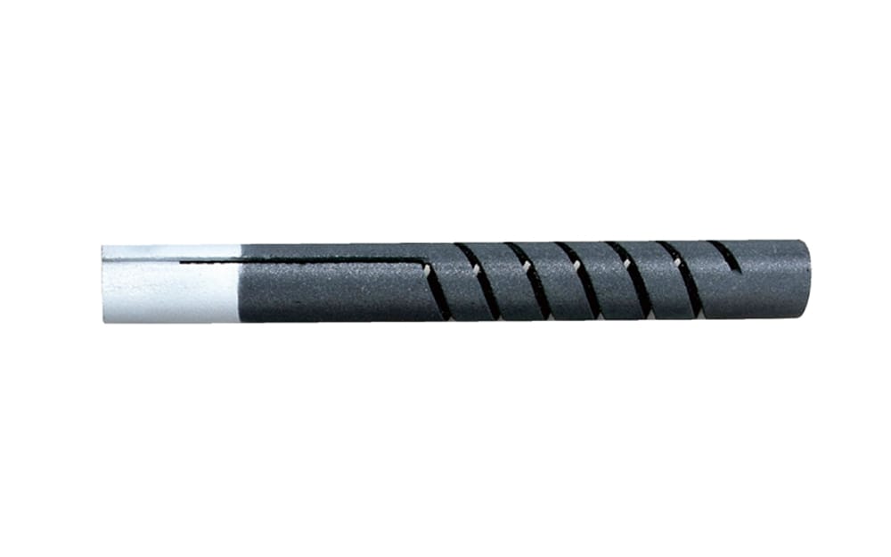
Qixiang Material provides several geometries, including the CU type silicon carbide rod, U-shaped silicon carbide rod, W-shaped silicon carbide rod, and SGR type silicon carbide rod. These are options to evaluate, not substitutes for the furnace heating zone design calculation.
Avoid concentrating all elements at one elevation simply because installation is easier. Check whether fixtures, trays, muffles, or product stacks shield radiation. Symmetric element count does not guarantee symmetric heating when the load and enclosure are asymmetric.
Convert zone duty into element count and surface loading
Calculate the power needed for useful load heating, fixtures, atmosphere, stored heat, and losses, then include the required recovery and control margin. Allocate that duty by region. Furnace heating zone design should show zone kilowatts, number of elements, watts per element, hot-zone surface area, expected surface loading, and the electrical arrangement.
Use the same operating case for every linked calculation. The SiC heating element power calculation guide explains how to move from zone requirements toward element-level voltage, current, and surface loading. In furnace heating zone design, repeat that process for each zone rather than dividing the total connected load by zone count.
Verify both new-element and aged-resistance conditions against transformer and controller limits. A zone that meets full power only at the end of its voltage range when new has little operating reserve. Element selection, circuit grouping, and control range have to be reviewed as one furnace heating zone design package.
Place control sensors where they represent the controlled result
A sensor close to an element can respond quickly while the load remains cold. A sensor hidden behind a fixture may cause the controller to overdrive exposed areas. Furnace heating zone design should distinguish control thermocouples, independent overtemperature sensors, and temporary survey sensors, with each location justified by the process.
Consider radiation, gas flow, conduction through the sheath or mounting, sensor immersion, response time, and access. NIST describes thermocouple calibration services and measurement uncertainties, reinforcing that a displayed number is only useful when the sensor and calibration suit the measurement. Furnace heating zone design also needs a calibration and replacement plan.
Do not use one sensor to compensate for a gradient it cannot observe. If two regions behave independently under real loads, separate sensing and control may be justified. If they always move together, insulation, element placement, or airflow changes may solve the problem more directly.
Prevent adjacent zones from fighting each other
Radiation and gas movement cross zone boundaries. Aggressive tuning can make neighbouring controllers alternate between high and low output, creating an average temperature that looks acceptable but a load history that is not. Furnace heating zone design should anticipate coupling and provide controller settings, output limits, and ramp logic that can be commissioned methodically.
Trend zone temperature, setpoint, controller output, current, voltage, door state, conveyor speed, and load identity on the same timeline. This reveals whether a disturbance starts with the process, a control response, or a loss of electrical output. Furnace heating zone design becomes easier to improve when the data preserves cause and sequence.
Commission with representative loads
Begin with verified wiring, resistance groups, sensor identification, controller limits, interlocks, and safe operating procedures. Then conduct staged heating and record electrical and temperature behaviour. Empty-chamber mapping can find gross problems, but furnace heating zone design should be accepted against representative production loads and agreed measurement locations.
Test light, normal, and heavy loading where these cases are permitted. Include door or conveyor disturbances that occur in service. Compare the load-temperature distribution, not just controller readings. Adjust one defined variable at a time and retain the before-and-after evidence.
The IEC 60519-1 overview describes general safety requirements for industrial electroheating installations. Project-specific design, safeguarding, commissioning, and energized measurements must be performed by qualified personnel under applicable requirements; this furnace heating zone design guide is not a substitute for that work.
Diagnose a weak zone before adding power
If a zone cannot recover, first determine whether it lacks commanded power, delivered electrical power, usable heat transfer, or measurement accuracy. Check controller output, secondary voltage, branch current, element resistance, connections, insulation, openings, atmosphere flow, sensor condition, and the load pattern. Adding elements without this diagnosis can hide the real furnace heating zone design problem.
Compare the weak zone with a healthy zone at the same process stage. Differences in current or voltage point toward the electrical system; similar electrical delivery with different load response points toward loss, placement, shielding, airflow, or sensing. Update the controlled furnace heating zone design documents after any approved change.
Frequently asked questions
How many heating zones should a furnace have?
Use enough zones to control materially different loads or losses. Chamber length alone is not a reliable rule; furnace heating zone design must consider doors, hearth, atmosphere flow, product movement, and sensor coverage.
Should every zone have the same power?
Not necessarily. Door, entry, exit, roof, and hearth regions may have different duties. Allocate power from the local load and heat-loss estimate used in the furnace heating zone design.
Where should the control thermocouple be installed?
Place it where its response represents the controlled process while avoiding misleading direct radiation or shielding. The correct location depends on chamber, load, airflow, and the purpose of that furnace heating zone design region.
Will more elements improve temperature uniformity?
Only if their power, position, surface loading, circuit, and control address the cause of the gradient. More connected load can worsen hot spots when furnace heating zone design is not corrected.
What data should be sent with an element inquiry?
Provide chamber and load drawings, zone duties, element positions, shape and dimensions, resistance, circuit arrangement, voltage range, temperature, atmosphere, cycle, quantity, and observed gradients. These details connect element selection to the actual furnace heating zone design.
Specify the zone as a complete operating system
Uniform heating comes from coordinated load definition, loss mapping, element placement, electrical capacity, sensing, control, and commissioning. Treating each as a separate purchase makes the gaps hard to find. A documented furnace heating zone design gives suppliers, furnace engineers, electricians, controls specialists, and production teams the same operating target.
For a new zone or replacement project, contact Qixiang Material with the furnace layout, required zone power, element drawing, circuit data, temperature, atmosphere, and quantity. The team can discuss suitable SiC element geometries while the responsible engineers approve the complete furnace and control system.