Choosing a heating element from kilowatts alone leaves an important question unanswered: how many amperes will the transformer secondary, controller, conductors, buswork, and connections actually carry? A SiC heating element current calculation must follow the circuit from the complete zone to each branch and finally to one element. Otherwise, a correct power target can still produce an impractical electrical design.
This guide gives furnace engineers, electrical designers, and maintenance teams a repeatable SiC heating element current calculation for single elements, series strings, parallel branches, and series-parallel zones. All examples are illustrative; qualified personnel must verify the actual equipment, protection, ratings, and applicable requirements.
Define which current you need to calculate
Start by drawing a boundary around the value you need. Element current, branch current, transformer secondary current, controller current, and incoming line current are not automatically equal. The SiC heating element current calculation should name the boundary, voltage, resistance, phase arrangement, and operating condition beside every result.
- Per-element current determines what passes through each element and terminal connection.
- Branch current is the current through one series string.
- Total secondary current is the sum of parallel branch currents for that controlled output.
- Primary and line current depend on the transformer, supply, phase arrangement, efficiency, power factor, and other project details.
Do not move between those levels without stating the conversion. A traceable SiC heating element current calculation is more valuable than a single answer with no circuit context.
Use Ohm’s law for one resistive element
For one element at a defined resistance and applied voltage, current is I = V/R. If power and voltage are known for the same element, I = P/V. If power and resistance are known, I = √(P/R). Each form gives the same result only when the inputs describe the same operating point. That consistency check should appear in every SiC heating element current calculation.
The NIST guidance on electrical SI units defines the relationships among amperes, volts, watts, and ohms. Keep units explicit: volts divided by ohms yields amperes. Avoid entering kilowatts as watts or milliohms as ohms in a SiC heating element current calculation worksheet.
Resistance needs a reference condition. Silicon carbide element resistance changes with temperature and service history, so an unqualified nameplate or room-temperature reading may not represent the design point. Record the manufacturer’s stated basis and the higher-resistance condition used to check control range in the SiC heating element current calculation.

Calculate a series string
Elements in series carry the same current. Add their resistances first: Rstring = R1 + R2 + … + Rn. Then divide the string voltage by that total resistance. The resulting branch value is also the current through every element in that string.
As an illustrative SiC heating element current calculation, three elements of 4 Ω each have a combined resistance of 12 Ω. With 120 V across the string, current is 120/12 = 10 A. Each element sees approximately 40 V only if the resistances are equal, and each delivers approximately 400 W at that stated condition.
If one element has higher resistance, the string current remains common but voltage and power no longer divide equally. Use the individual resistances to calculate each voltage drop and power. A SiC heating element current calculation for replacement work should therefore include a resistance-matching rule, not merely the number of elements. Retain that SiC heating element current calculation with the approved branch schedule.
Calculate parallel branches
Parallel branches share the same supply voltage, and their currents add. Calculate each branch separately with Ibranch = V/Rbranch. Then sum all branch currents to find the controlled secondary current. This is the central SiC heating element current calculation for buswork, controller output, and transformer secondary loading.
For three identical 12 Ω branches at 120 V, each branch draws 10 A and the total is 30 A. If one branch is 15 Ω, it draws 8 A while the other two remain at 10 A, so total current becomes 28 A. Equal voltage does not create equal branch power when resistance differs.
Show one row per branch in the SiC heating element current calculation. A single “equivalent resistance” answer can predict total current but hides the imbalance that maintenance needs to see.
Work through a series-parallel zone
Most larger zones are easiest to review branch by branch. Suppose a zone has four parallel branches, each with two 5 Ω elements in series. Each branch is 10 Ω. At 100 V secondary, each branch draws 10 A, so the zone draws 40 A and delivers 4 kW at that illustrative condition.
| Calculation level | Equation | Illustrative result |
|---|---|---|
| One branch resistance | 5 Ω + 5 Ω | 10 Ω |
| One branch current | 100 V / 10 Ω | 10 A |
| One branch power | 100 V × 10 A | 1,000 W |
| Zone current | 4 branches × 10 A | 40 A |
| Zone power | 100 V × 40 A | 4,000 W |
Cross-check the SiC heating element current calculation with P = V × I at branch and zone level. If summed branch power does not match secondary voltage multiplied by total current, inspect the boundaries, units, and phase assumptions before proceeding.
The worked values are not a recommended furnace rating. Actual resistance, surface loading, element type, chamber conditions, voltage range, and component ratings must come from the approved design.
Calculate from required zone power
If required zone power and secondary voltage are known for a resistive single-phase output, current is I = P/V. For a 24 kW zone at 240 V, the ideal resistive current is 100 A. This top-down SiC heating element current calculation is useful for early equipment sizing, but it does not define the branch arrangement or confirm element suitability.
Next divide the zone into practical branches, calculate the required branch resistance, and verify voltage per element, watts per element, and surface loading. The SiC element power calculation guide covers the thermal and surface-loading checks that must accompany the SiC heating element current calculation.
For three-phase arrangements, do not apply a memorized line-current equation until the transformer secondary and load connection are confirmed. Delta, wye, single-phase branch distribution, unbalance, controller topology, and measurement location affect what “current” means. The responsible electrical engineer must calculate the actual system.
Check controller, transformer, and connection capacity
The calculated steady value is not the entire equipment specification. Review permissible overload, controller operating mode, transformer tap range, conductor temperature, terminal environment, protection, duty cycle, harmonics where applicable, enclosure conditions, and derating. A complete SiC heating element current calculation should list the design current separately from the selected component rating. Mark all derating assumptions directly on the SiC heating element current calculation.
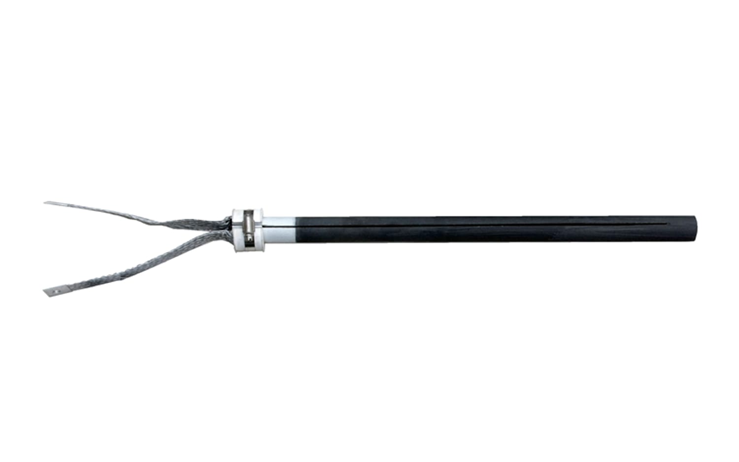
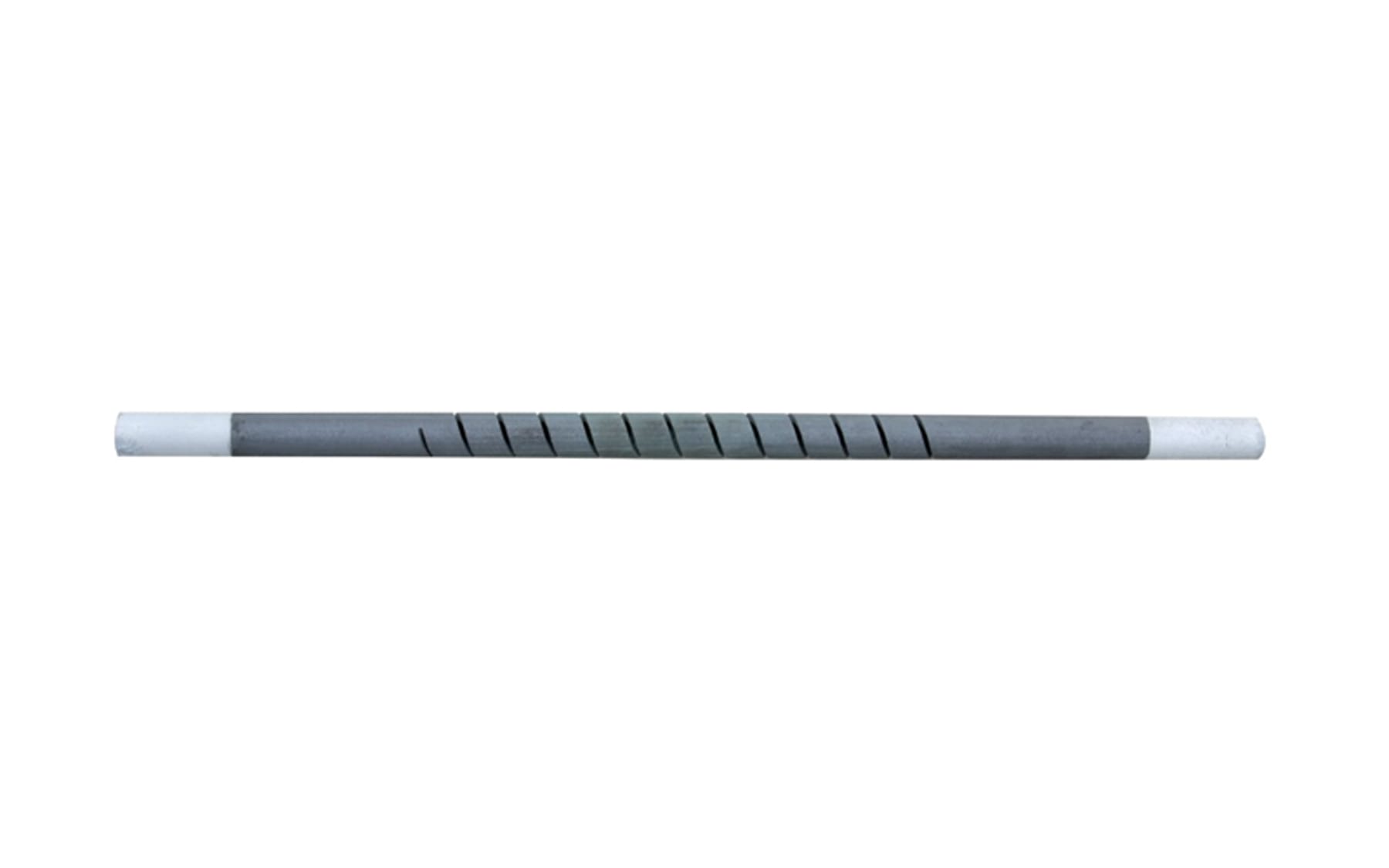
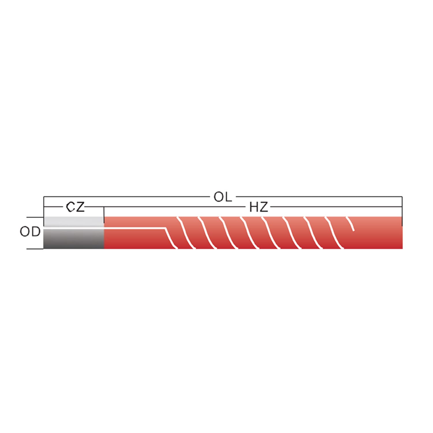
Use the SiC heating element wiring diagram guide to document series and parallel grouping. Also specify compatible element connections. Product options include aluminum conductive strips and a heating rod clamp, subject to the approved element and furnace design.
OSHA provides an overview of applicable electrical standards, while the IEC 60519-1 page describes general safety requirements for industrial electroheating installations. Project requirements govern design and installation; an online SiC heating element current calculation is not a safety approval.
Allow for resistance increase in service
As element resistance increases, maintaining the same power requires a higher voltage, while current at that same power follows I = P/V. The controller and transformer must provide a usable operating range without exceeding their limits. Run the SiC heating element current calculation at the approved new-element condition and at the defined higher-resistance design condition.
Do not add an arbitrary aging percentage unless the element supplier and furnace design support it. Document the assumed resistance range, voltage reserve, tap or control strategy, and replacement threshold. That turns the SiC heating element current calculation into a lifecycle check rather than a one-time arithmetic result.
Verify current during commissioning
Before energization, verify installed element resistance groups, circuit connections, transformer configuration, controller limits, protection, grounding or bonding, and safe isolation. During staged startup, qualified personnel can record secondary voltage and each accessible branch current with approved instruments and procedures.
Compare measurements only at the same operating condition. Controller output, temperature, tap position, and load state should accompany each value. NIST Technical Note 1297 explains principles for expressing measurement uncertainty; the project team should apply an appropriate method when comparing results with the SiC heating element current calculation.
A low-current branch may indicate higher resistance, a connection issue, an open element, incorrect grouping, or measurement at a different control state. Do not replace elements solely because one current differs. Use voltage, resistance, thermal behaviour, and inspection evidence together.
Build a reusable calculation sheet
Use one row per element and one summary per branch. Record element position, resistance basis, grouping, branch voltage, element voltage, branch current, element power, branch power, total current, and the higher-resistance check. Add units and formula references instead of leaving unexplained spreadsheet constants.
Lock input and result cells separately, add range checks, and require an independent review before release. A controlled SiC heating element current calculation can then support quotations, design reviews, commissioning, and later replacement decisions without losing its assumptions.
Frequently asked questions
Is current the same through elements in series?
Yes, the same branch current flows through series components. Voltage and power can differ when their resistances differ, so a SiC heating element current calculation should also check individual voltage drops.
How do I find total current for parallel branches?
Calculate each branch from its voltage and total branch resistance, then add branch currents. Do not multiply one value unless all branches are confirmed equal in the SiC heating element current calculation.
Can I calculate current from kilowatts?
For a resistive output with power and voltage defined at the same boundary, I = P/V. A complete SiC heating element current calculation still needs the actual phase and branch arrangement.
Why is measured current lower after long service?
Resistance may have increased, but controller output, voltage, tap position, connection condition, and measurement state can also explain the change. Collect all values before deciding.
What information should I send to an element supplier?
Provide the element drawing, resistance basis, quantity, wiring arrangement, transformer secondary range, zone power, measured voltage and current, temperature, atmosphere, and cycle. Include the SiC heating element current calculation sheet if available.
Make every amp traceable to an element and branch
A reliable result starts with the correct electrical boundary, not a calculator button. Work from element resistance to series strings, parallel branches, and total secondary loading; then repeat the check across the planned resistance and voltage range. A documented SiC heating element current calculation makes design reviews and field measurements much easier to reconcile.
For element selection or replacement, contact Qixiang Material with the drawing, circuit, resistance, voltage range, power requirement, furnace temperature, atmosphere, and quantity. The team can discuss suitable SiC elements and connection accessories while qualified engineers approve the complete electrical system.