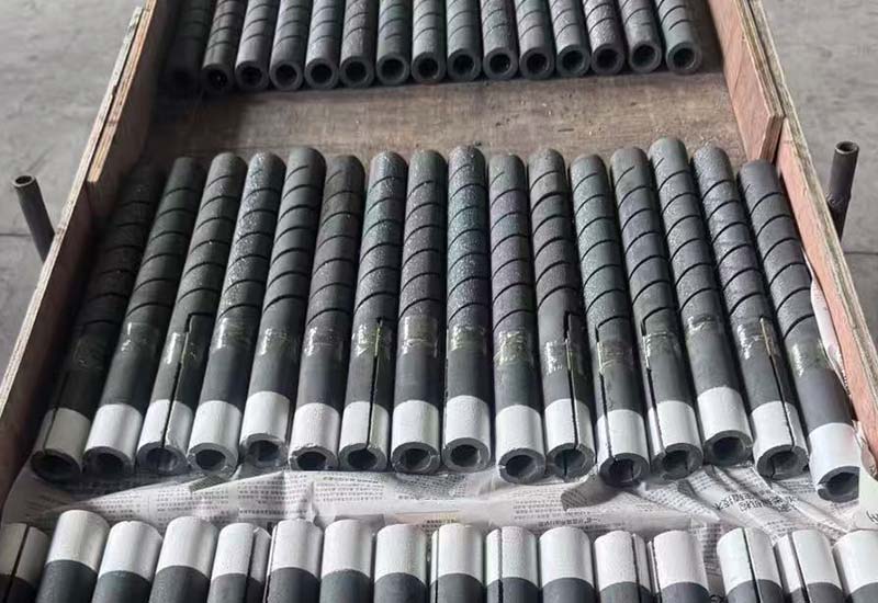
A furnace can have enough installed kilowatts and still run out of control authority. New silicon carbide elements may need relatively low secondary voltage, while elements with higher service resistance need more voltage to deliver the same power. SiC heating element voltage control has to cover both conditions without forcing the controller to live at its minimum or maximum output.
This guide explains how to define a useful SiC heating element voltage control window, coordinate transformer taps with electronic control, and establish evidence-based adjustment rules. It is intended for furnace engineers, controls teams, and maintenance managers reviewing a new design or an aging element system.
Begin with power and resistance, not a preferred tap
For a resistive element or branch, voltage at a stated operating point follows V = √(P × R). If required power stays constant while resistance rises, required voltage rises with the square root of resistance. This relationship is the starting point for SiC heating element voltage control, but only when power and resistance describe the same electrical boundary.
- Define required power for one element, one branch, or one complete zone.
- Use resistance for that same boundary and identify its reference condition.
- Calculate required voltage at the new-element condition.
- Repeat at the approved higher-resistance design condition.
- Compare both results with transformer, controller, conductor, and protection limits.
The NIST overview of electrical SI units provides the unit relationships among volts, amperes, watts, and ohms. Keep those units visible on the SiC heating element voltage control worksheet to prevent a branch value from being mixed with a per-element value.
Calculate a voltage envelope instead of one setpoint
A single calculated voltage is not a lifecycle plan. Build a small operating matrix that includes the lowest approved resistance, normal new-element resistance, one or more intermediate states, and the defined replacement or maximum design resistance. For every row, the SiC heating element voltage control review should show voltage, current, power, controller output range, and transformer tap.
| Operating state | Required check | Control question |
|---|---|---|
| New elements, lowest approved resistance | Voltage and current at required power | Can output be controlled without operating too close to the minimum? |
| New elements, nominal resistance | Normal duty and recovery duty | Is useful modulation available? |
| Elements after service | Measured branch resistance and available power | Is a tap change justified by trend data? |
| Higher-resistance design limit | Maximum required voltage and component limits | Does sufficient control reserve remain? |
| Abnormal branch imbalance | Individual voltage, current, resistance, and connections | Is this a control issue or a branch fault? |
Use approved project values rather than a generic aging percentage. The element supplier, furnace designer, and controls engineer should agree on the resistance envelope that the SiC heating element voltage control system is expected to serve.
Separate coarse transformer range from fine modulation
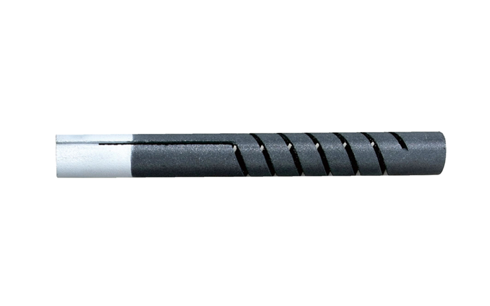
Transformer taps establish the secondary voltage range; the power controller modulates within that range. A practical SiC heating element voltage control strategy uses the tap as a coarse adjustment and leaves the controller enough room to regulate normal load changes, door recovery, and production variation.
Beginning service on the highest tap can leave no later-life reserve. Beginning on a tap that forces the controller to operate near its lowest effective output can reduce controllability and make commissioning difficult. For each tap, calculate available branch voltage and plot the expected operating band before approving SiC heating element voltage control.
A tap change should follow a controlled isolation and approval process, not become an operator’s response to every slow recovery. The OSHA control of hazardous energy standard is relevant to U.S. servicing practices. Site procedures and applicable requirements govern work on the SiC heating element voltage control equipment.
Choose controller operation for the complete power system
Phase-angle, burst or zero-cross, and other control methods affect transformers, supply systems, measurement, harmonics, and process response differently. There is no universal mode that is best for every furnace. The SiC heating element voltage control design must follow the approved transformer and controller combination, plant electrical requirements, and required temperature response.
Confirm the controller’s output definition. A displayed percentage may represent firing command, duty cycle, or another internal quantity rather than measured RMS secondary voltage. Commission SiC heating element voltage control with suitable voltage and current measurements instead of treating screen percentage as electrical proof.
For multiple zones, check shared transformer or supply constraints. One zone recovering at high output can affect another through voltage drop, demand limits, or supervisory logic. Trend all related zones when diagnosing apparent voltage-control instability.
Check current and surface loading at every voltage state
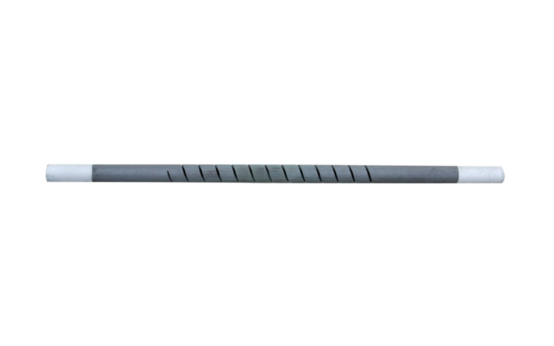
Raising voltage changes power and current; it is not an isolated control adjustment. For every candidate tap and resistance state, calculate current with I = V/R and power with P = V²/R. Then confirm element surface loading, transformer current, controller rating, conductors, straps, clamps, and protection. SiC heating element voltage control cannot be approved from voltage alone.
The SiC current calculation guide explains element, branch, and total secondary amperes. The power calculation guide connects electrical power with element surface area. Use both checks beside the SiC heating element voltage control matrix.
Do not use increased voltage to compensate indefinitely for damaged insulation, open doors, reduced element count, weak connections, or an overloaded process. If required output moves unexpectedly, diagnose the thermal and electrical system before changing the SiC heating element voltage control range.
Use different logic for cold startup, hot restart, and production
A cold furnace, a normal loaded cycle, and a hot restart do not present the same thermal state. Define output limits and ramp behaviour for each permitted condition. SiC heating element voltage control should prevent an uncontrolled jump to the maximum available output after a trip or temporary loss of process feedback.
Coordinate element needs with refractory, load, atmosphere system, and process limits. A slower ramp may be required by the furnace or product even when the element circuit could accept more power. The U.S. Department of Energy’s process heating resources emphasize a system view; the same principle applies when defining SiC heating element voltage control recipes.
After any trip, identify the cause, verify the furnace state, and use the approved recovery sequence. Do not bypass an interlock or increase a tap merely to recover temperature faster.
Create evidence-based tap-change criteria
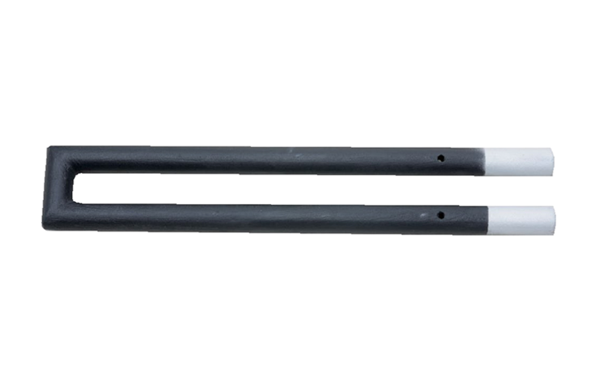
Use trends rather than calendar age. Record branch resistance, secondary voltage, current, controller output, tap, zone temperature, load, and recovery time at comparable operating conditions. SiC heating element voltage control decisions are credible only when the data distinguishes resistance growth from changing production duty.
- Investigate a zone that reaches high output only on certain products.
- Compare branch currents before assuming all elements have aged equally.
- Inspect terminals and conductor condition when voltage is present but branch power is low.
- Verify sensor calibration and placement when controller output conflicts with load temperature.
- Change taps only after the approved trigger and safe work process are satisfied.
Write the trigger as a measurable condition. “Increase voltage when old” is not adequate. A usable SiC heating element voltage control instruction identifies who reviews the trend, which measurements are required, what limits apply, and how the new setting is documented.
Recognize problems that voltage cannot solve
Unequal branches, localized terminal heating, open elements, poor resistance matching, incorrect series grouping, insulation loss, atmosphere changes, and sensor error can all appear as a need for more output. Compare measured voltage with current and resistance before changing SiC heating element voltage control.
If one branch draws less current at the same applied voltage, calculate its resistance and inspect its complete path. If all branches behave similarly but the load remains cold, investigate losses, element placement, load changes, and temperature measurement. A zone-wide tap change can mask a branch fault while stressing healthy elements.
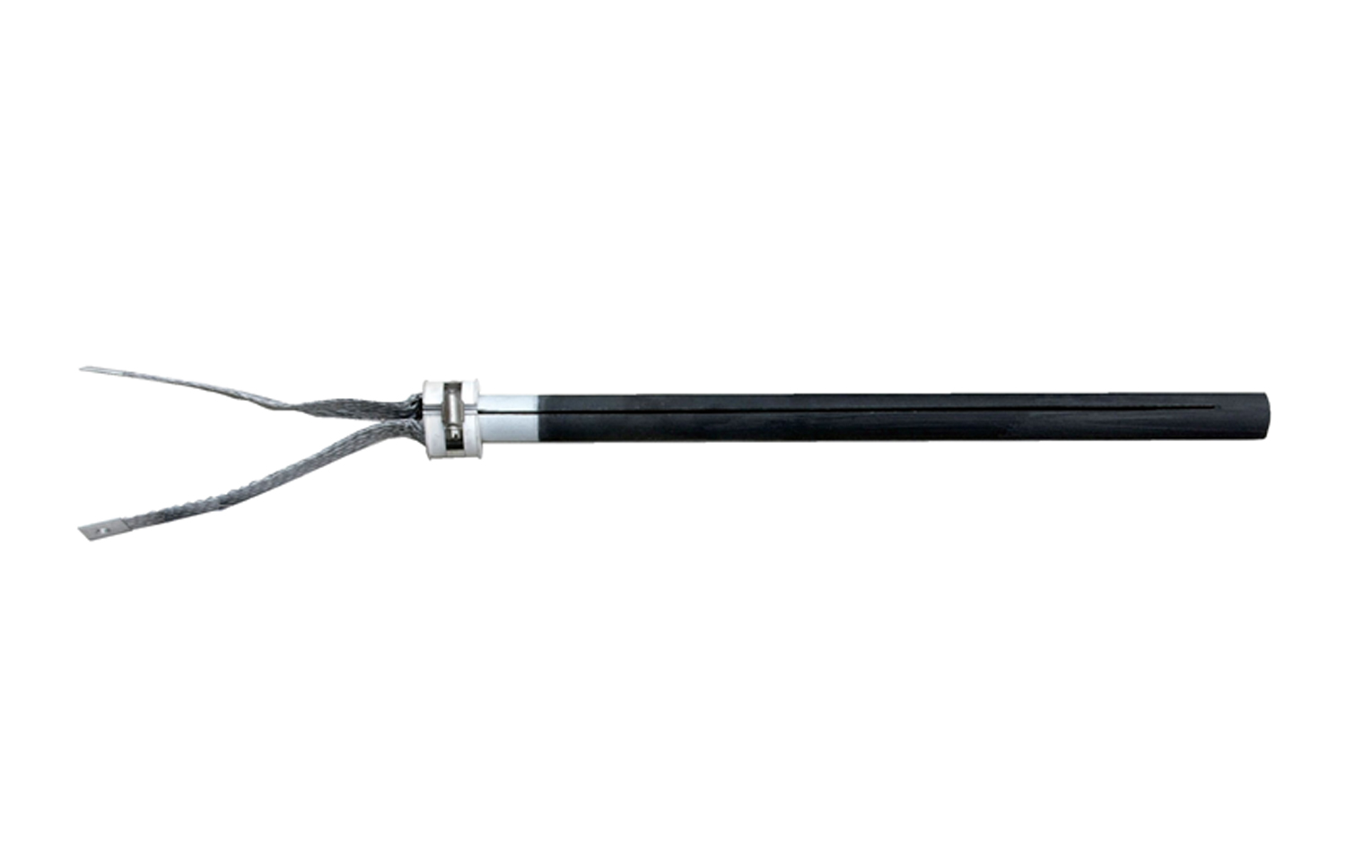
Use the SiC wiring diagram guide to document branch grouping and test points. That drawing should agree with the live SiC heating element voltage control configuration and the resistance history.
Document settings for commissioning and maintenance
The handover package should record transformer connections and taps, controller model and approved mode, limits, element and branch resistance, expected voltage and current bands, startup recipes, tap-change criteria, test points, protection, interlocks, and authorized roles. Put the same revision identifier on the SiC heating element voltage control sheet and wiring diagram.
During commissioning, test staged output at approved conditions and compare measured RMS voltage and current with calculations. Retain baseline data for each zone. The IEC 60519-1 page describes the scope of general safety requirements for industrial electroheating installations; qualified engineers must apply the standards and local requirements relevant to the project.
After an approved change, record the previous and new tap, reason, authorizer, measurements, date, and resulting process behaviour. This history prevents future SiC heating element voltage control troubleshooting from beginning with guesswork.
Frequently asked questions
Why do aged SiC elements need more voltage?
When resistance rises, more voltage is needed to deliver the same power. The approved SiC heating element voltage control range should anticipate a defined resistance envelope rather than an unlimited increase.
When should a transformer tap be changed?
Change it only under the approved criteria, after comparable trend data shows that resistance and required duty have moved beyond the useful band of the current SiC heating element voltage control setting.
Is 100% controller output acceptable?
Brief operation may be part of an approved sequence, but persistent saturation means no upward control authority remains. Investigate load, losses, resistance, circuit condition, and voltage range.
Can voltage be increased when one branch is weak?
Not as a first response. Measure voltage, current, and resistance by branch and inspect the circuit. A system-wide SiC heating element voltage control change may overdrive healthy branches.
What data should be sent for a replacement review?
Send the element drawing, resistance basis and history, wiring, transformer secondary range, taps, controller details, measured voltage and current, temperature, atmosphere, cycle, quantity, and present SiC heating element voltage control limits.
Protect control authority across the element life cycle
The objective is not the highest available voltage. It is a documented operating window that controls new elements, supplies later-life voltage reserve, respects electrical and thermal limits, and gives maintenance a clear adjustment rule. Well-planned SiC heating element voltage control connects resistance history with actual furnace duty.
For a new furnace or replacement review, contact Qixiang Material with the element drawing, branch arrangement, resistance range, zone power, transformer range, controller information, operating temperature, atmosphere, and quantity. The team can discuss suitable SiC elements while the responsible engineers approve the complete power and control system.