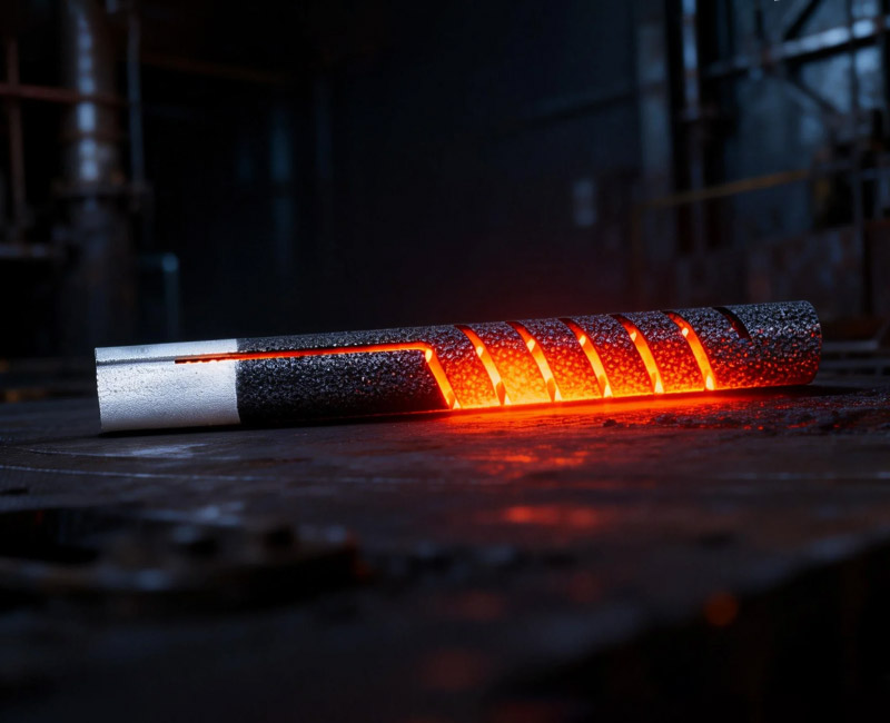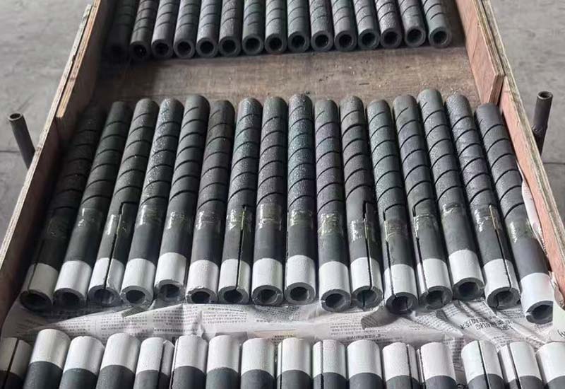
Choosing an element only by length, diameter, and resistance can produce a furnace that reaches temperature but consumes element life too quickly. The missing check is often SiC heating element watt density: the electrical power released over the active radiating surface of the hot zone.
Watt density is not a universal rating that can be copied from one furnace to another. Chamber temperature, atmosphere, element geometry, heat transfer, cycling pattern, and the arrangement of nearby elements all influence the acceptable operating point. This guide shows furnace designers and technical buyers how to calculate SiC heating element watt density and how to use it as one part of a complete selection review.
What SiC heating element watt density actually measures
SiC heating element watt density is the power dissipated by one element divided by the external surface area of its active heating section. It may be stated in watts per square centimeter or watts per square inch. The calculation excludes cold ends because their purpose is to carry current through the furnace wall with much less heat release.
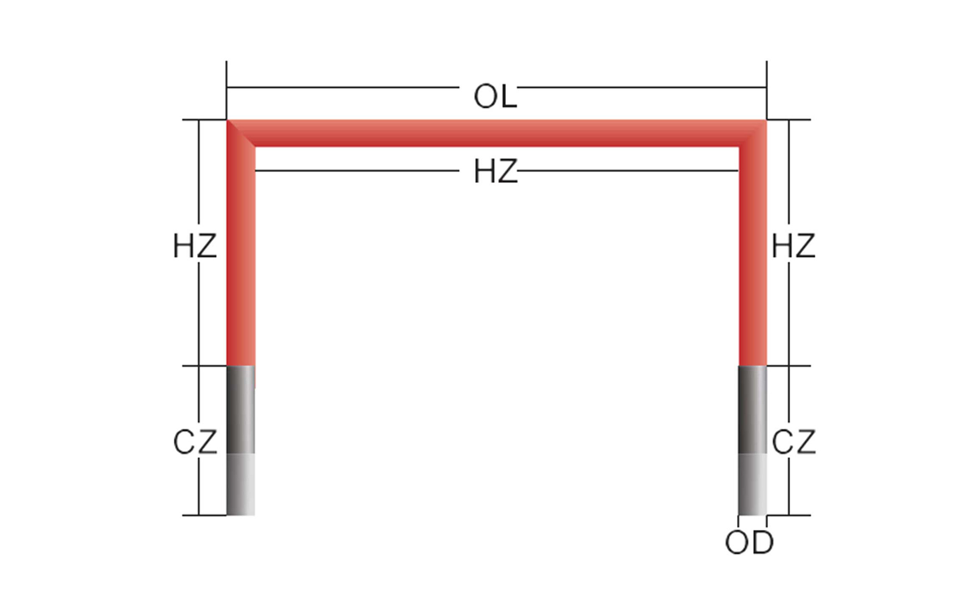
For a straight cylindrical hot zone, active surface area is approximately π × diameter × hot-zone length. Divide element watts by that area to obtain SiC heating element watt density. For grooved, hollow, U-shaped, W-shaped, or multi-leg designs, confirm which dimensions and surfaces the supplier uses. A simple cylinder formula can misrepresent a shape with multiple active legs or a machined resistance path.
The NIST guide to SI electrical units is a useful reference for volts, amperes, ohms, and watts. Keep those electrical units separate from surface-area units on the worksheet so the SiC heating element watt density result can be checked without guessing how a conversion was made.
Start with zone heat duty, not a preferred watt density
A sound design begins with the required power for each furnace zone. Estimate the energy needed to heat the product, fixtures, and relevant furnace mass within the allowed time, then add continuing wall, opening, exhaust, infiltration, and process losses. Only after zone power is justified should the designer select the number and geometry of elements.
Dividing zone kilowatts by the number of elements gives target watts per element. Combining that result with the active surface area gives the first SiC heating element watt density estimate. If the value is too demanding for the atmosphere and temperature, the engineering response is usually to increase active surface area, add elements, redistribute zone load, or reconsider the furnace layout—not to assume the element will tolerate the target.
The U.S. Department of Energy’s process heating resources emphasize a systems approach to industrial heating. That principle applies directly here: SiC heating element watt density cannot compensate for unmeasured door loss, excessive air leakage, weak insulation, or a zone that has been assigned more duty than its geometry can radiate effectively.
Calculate active surface area correctly
Use the actual hot-zone length, not the total element length. On a straight rod, the transition between the hot zone and cold ends should be identified on the supplier drawing. Measure diameter consistently and state whether the value is nominal or measured. For a tubular element, SiC heating element watt density normally uses external radiating area unless the approved supplier method states otherwise.
- Straight rod: calculate the outside area of the active cylindrical section.
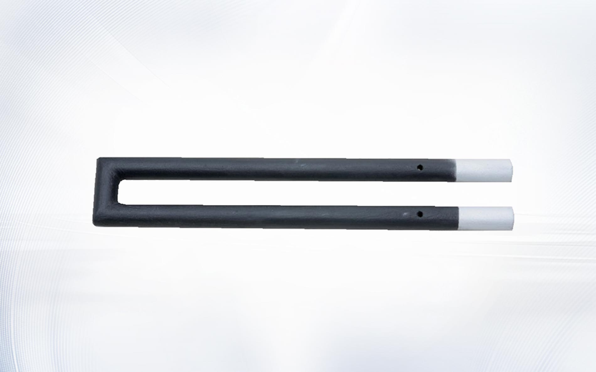
- U-shaped element: calculate both active legs and the active bend according to the drawing.
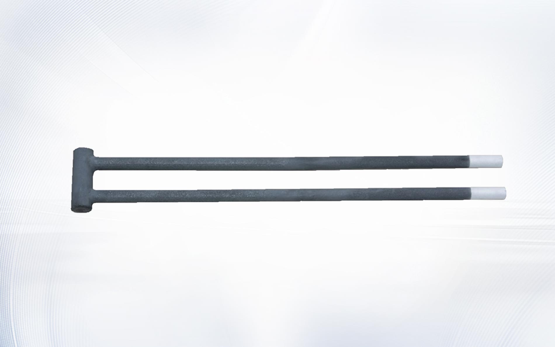
- W-shaped element: include all active legs and bends while excluding cold terminal sections.
- Spiral or grooved element: use the supplier’s defined active area rather than estimating the groove surface independently.
- Custom element: request a drawing that marks hot zone, cold ends, diameter, and the area basis used for SiC heating element watt density.
A drawing-controlled calculation avoids a costly communication problem: one party may divide power by the apparent envelope area while another uses the developed element surface. Both results can look mathematically correct, yet they describe different SiC heating element watt density values.
Account for chamber temperature and heat transfer
An element transfers heat to the load, refractories, fixtures, and furnace atmosphere through radiation, convection, and conduction at supports or terminals. As chamber temperature rises, the element has less temperature difference available to reject a given amount of power. The same SiC heating element watt density can therefore produce a different element temperature in a cold test than during a high-temperature production soak.
View factor matters as well. Closely spaced elements, a reflective load, shielding, deep recesses, or an element facing another hot element can reduce effective heat release. Do not apply SiC heating element watt density without checking spacing and line of sight. Local shielding can create a hot segment even when the average value for the full hot zone appears acceptable.
Material-property references such as the NIST Ceramics Data Portal for silicon carbide help distinguish general material behavior from a finished heating-element specification. The project limit for SiC heating element watt density must still come from the element supplier for the intended temperature, geometry, and atmosphere.
Adjust the review for furnace atmosphere
Atmosphere can change oxidation behavior, surface condition, resistance growth, and the ability of the element to dissipate heat. Air, inert gas, reducing gas, vacuum, water vapor, process volatiles, and deposits should not be treated as equivalent. Record gas composition, flow, pressure, dew point or moisture condition where relevant, and any binders or vapors released by the load.
A supplier may recommend a lower SiC heating element watt density for a demanding atmosphere or intermittent process than for clean continuous operation in air. Use application-specific guidance rather than copying a limit from an unrelated furnace. If the atmosphere changes during a cycle, evaluate the worst credible combination of gas condition, chamber temperature, and element output.
Deposits deserve a separate check. A coating of process material can insulate part of the hot zone, alter emissivity, or create chemical attack. Average SiC heating element watt density does not reveal that local condition, so inspection access and cleaning practices belong in the design review.
Check cycling, control method, and power overshoot
Thermal cycling can be more demanding than a stable soak because the element, supports, furnace wall, and load expand at different rates. Fast power application also creates temperature gradients within the element. A SiC heating element watt density that is acceptable at steady state may still require a controlled startup or reduced initial output.
Review the actual power-control method. Phase-angle control, burst firing, transformer taps, and contactor control produce different electrical and thermal behavior. The worksheet should state whether SiC heating element watt density is based on average delivered power, maximum continuous power, or another approved condition. Short peaks must be evaluated by the responsible electrical and furnace engineers rather than ignored by an averaging calculation.
Industrial electroheating installations also require system-level safety engineering. The IEC 60519-1 overview describes the scope of general safety requirements for electroheating installations. The applicable current edition and local regulations should be confirmed for the project; SiC heating element watt density is not a substitute for electrical protection, interlocks, guarding, or safe commissioning.
Use a two-point electrical check for new and aged elements
Element resistance changes during service. For a fixed voltage, higher resistance reduces power; for constant target power, higher resistance requires more voltage. The transformer and controller must cover a practical operating window without exceeding current limits at the low-resistance condition or voltage limits at the higher-resistance condition.
Calculate SiC heating element watt density at the intended normal point and the maximum approved power point. Then test the corresponding voltage and current for the defined new- and aged-resistance cases. This separates two questions that are sometimes confused: whether the element surface can release the heat and whether the electrical system can deliver it throughout the planned service interval.
| Review item | Input to document | Question the calculation must answer |
|---|---|---|
| Heat duty | Zone kW and operating cycle | How many watts must each element deliver? |
| Active area | Hot-zone geometry and dimensions | What SiC heating element watt density results? |
| Thermal environment | Chamber temperature, spacing, view factor | Can the surface reject the required heat? |
| Atmosphere | Gas composition, moisture, deposits | Does the application require a lower operating point? |
| Electrical range | Resistance, voltage, current, transformer taps | Can the system serve new and aged elements safely? |
Work through an illustrative calculation
Assume a hypothetical straight element is assigned 3,600 W and has an active diameter of 40 mm with a 600 mm hot zone. Its approximate external active area is π × 4 cm × 60 cm, or about 754 cm². Dividing 3,600 W by 754 cm² gives an SiC heating element watt density of about 4.8 W/cm².
This example only demonstrates the arithmetic. It does not establish a permissible SiC heating element watt density for a real furnace. The design still needs supplier confirmation for element type, chamber temperature, atmosphere, mounting, cycling, spacing, and resistance range. A U-shaped or grooved element also requires the area method defined for that geometry.
If the initial SiC heating element watt density is too high, compare practical alternatives: add elements, lengthen the active zone, use a geometry with more active area, reduce zone duty through furnace-loss improvements, or redistribute power. Changing diameter or resistance without checking voltage, current, openings, and supports can solve one constraint while creating another.
Select element geometry around the furnace layout
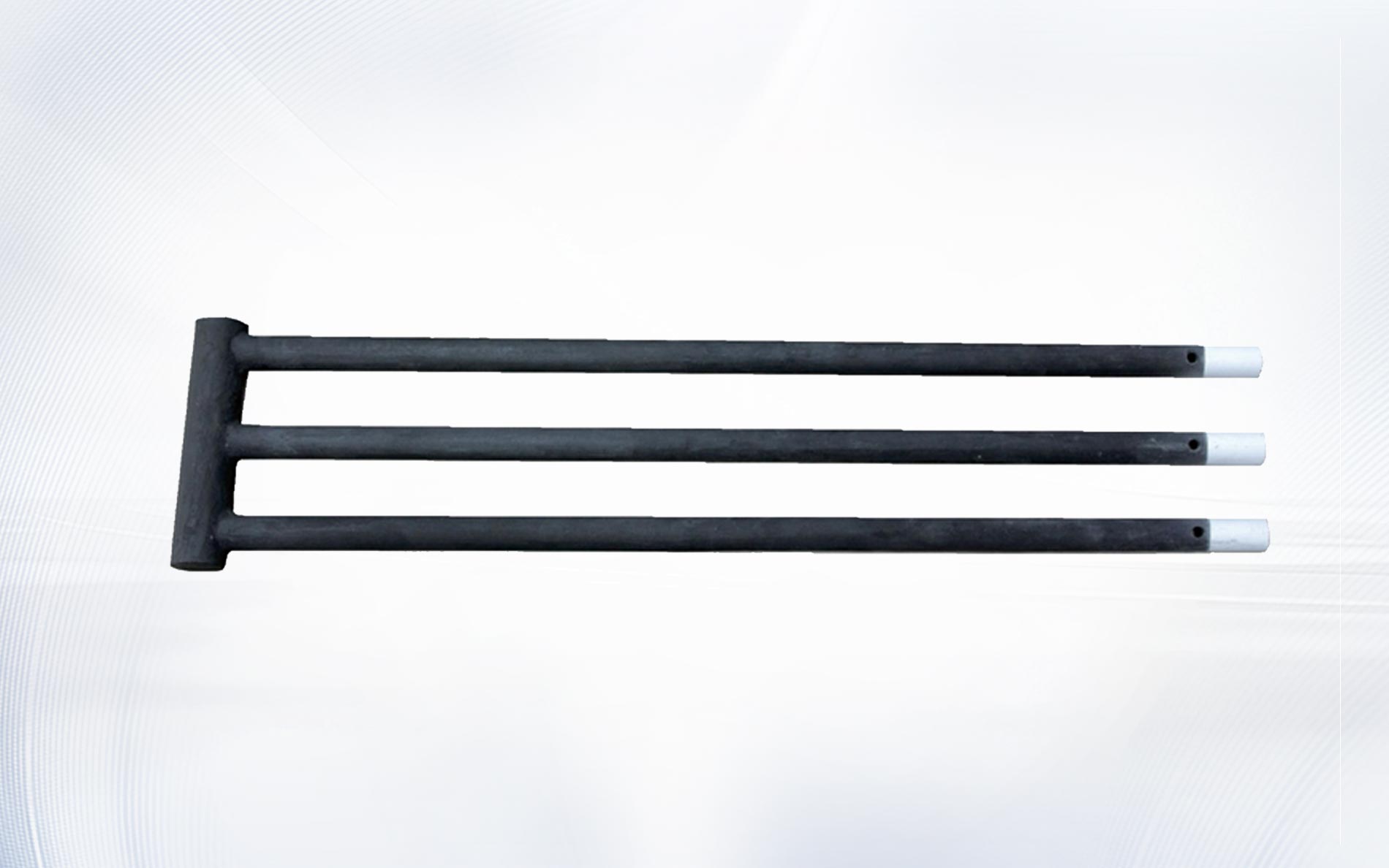
Element shape determines how much active area fits in the available chamber and where the terminals can be placed. A CU type silicon carbide rod may suit a compact single-ended arrangement, while a U-shaped silicon carbide rod or W-shaped silicon carbide rod can provide multiple active legs with connections on one side.
The V-shaped silicon carbide heating rod offers another layout option where the furnace design calls for that form. Compare geometries using hot-zone coverage, SiC heating element watt density, resistance, voltage, current, support, terminal access, and replacement clearance. Shape selection should be the result of those checks, not a cosmetic preference.
Frequently asked questions
Is higher watt density always better?
No. Higher SiC heating element watt density can reduce the number or length of elements, but it can also increase element temperature and reduce operating margin. The acceptable value depends on the complete furnace application.
Should cold ends be included in the surface-area calculation?
Normally, SiC heating element watt density is calculated from the active hot-zone area. Use the supplier drawing to identify transitions and confirm the area method for the selected element.
Can the same watt density be used for air and reducing gas?
Do not assume so. Atmosphere changes element behavior and can alter the recommended SiC heating element watt density. Provide gas composition, flow, pressure, moisture, and process-vapor information to the supplier.
Does resistance aging change watt density?
It changes the voltage required to maintain the same power. If the controller maintains element watts, SiC heating element watt density can remain similar while voltage rises and current falls. Both thermal and electrical limits must still be checked.
What information should be sent with an RFQ?
Send furnace temperature, atmosphere, cycle, zone power, element quantity, hot- and cold-zone dimensions, diameter, shape, resistance condition, circuit arrangement, voltage range, mounting drawing, and the proposed SiC heating element watt density.
Turn watt density into a complete element specification
SiC heating element watt density is most useful as a screening and comparison tool. It connects zone power to active surface area, but it must be reviewed alongside atmosphere, chamber temperature, element spacing, shape, resistance, voltage range, cycling, mounting, and controls. Keeping those inputs on one calculation sheet makes supplier review and internal approval much clearer.
For a new design or replacement project, contact Qixiang Material with the furnace drawing and operating conditions. The team can review element geometry and electrical requirements while your responsible engineers confirm system safety, protection, installation, and commissioning.