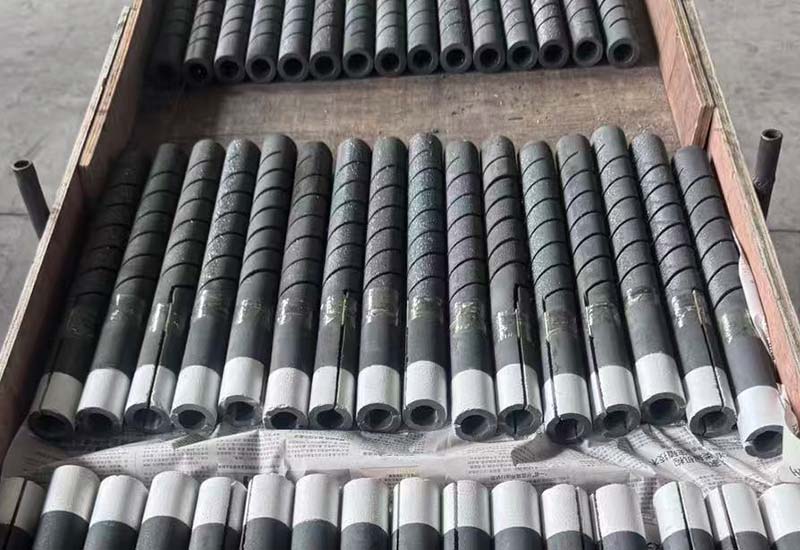
A replacement SiC element can have the correct overall length and still be unusable. If the terminal section stops inside the insulation, the connection runs too close to the hot face, or the diameter does not fit the existing opening, installation becomes a furnace modification rather than a routine replacement. The silicon carbide heating element cold end therefore needs its own drawing and acceptance criteria.
This guide shows furnace owners, maintenance teams, and technical buyers how to specify a silicon carbide heating element cold end without relying on an incomplete model name. It separates the dimensions that control mechanical fit from the electrical and operating data that determine element performance.
What the cold end has to accomplish
The terminal section carries current from the external connection toward the hot zone while passing through the furnace wall. A correctly selected silicon carbide heating element cold end must place the connection where it can be reached, supported, inspected, and kept within the limits of the complete installation.
- It passes through the refractory or insulation without forcing the hot zone out of position.
- It provides enough accessible length for the conductive strap and clamp.
- It matches the existing opening, support, and terminal arrangement.
- It avoids unwanted heating at the wall penetration and connection point.
- It allows reasonable movement as the furnace heats and cools.
These jobs are related, but they are not interchangeable. Increasing one silicon carbide heating element cold end dimension cannot automatically correct an unsuitable diameter, terminal position, or element shape.
Record five dimensions before requesting a replacement
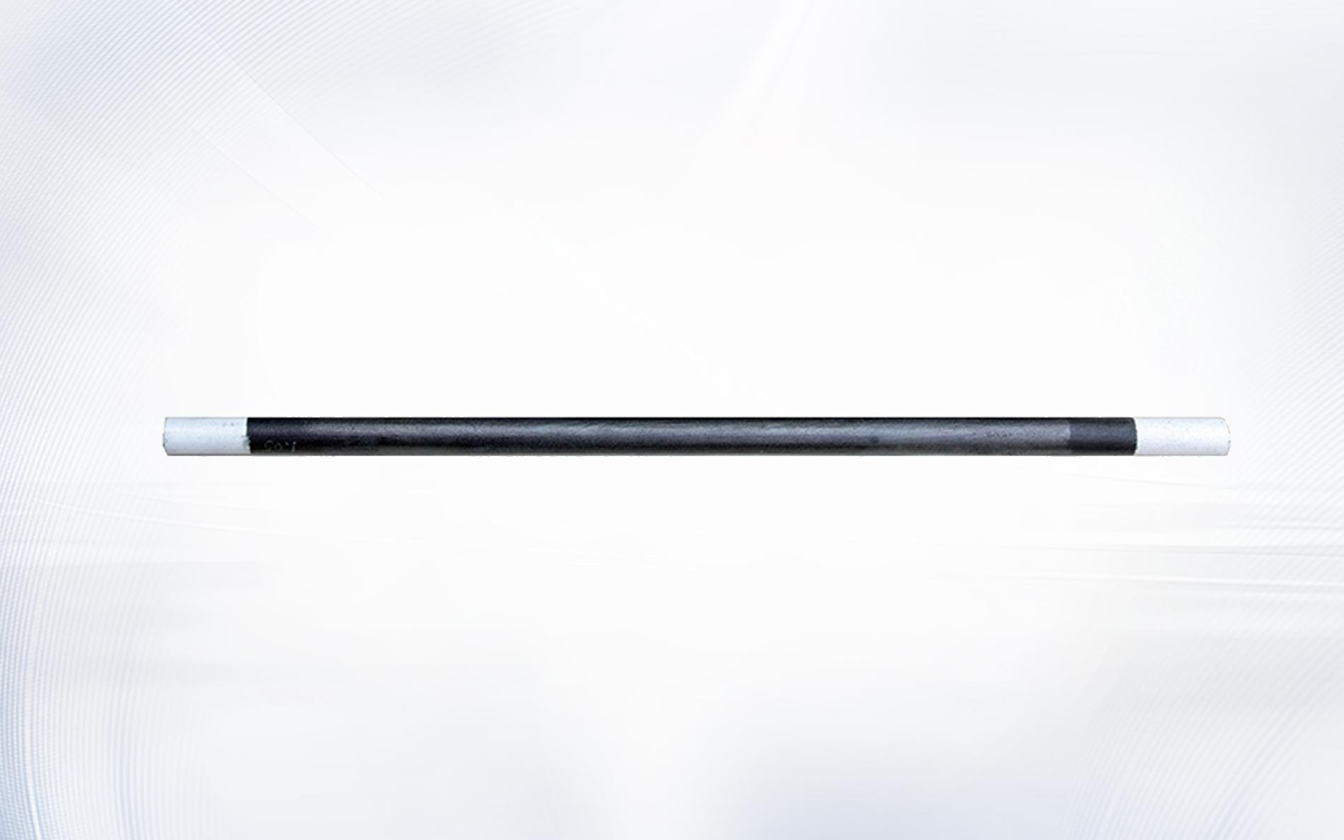
Do not measure only the old element from tip to tip. A useful silicon carbide heating element cold end specification records the overall length, hot-zone length, cold-end length on each side, outside diameter, and terminal treatment or connection area. If the two ends are not identical, label the left and right ends separately.
| Drawing field | Why it matters | Common purchasing error |
|---|---|---|
| Overall length | Controls total fit across the chamber and outside access | Copied without checking hot-zone location |
| Hot-zone length | Defines the intended radiating section inside the chamber | Confused with chamber width |
| Cold-end length, side A and B | Locates the wall passage and connections | Assumed to be equal |
| Element diameter | Affects opening clearance, support, and electrical design | Estimated from a photograph |
| Terminal area and treatment | Determines how the strap and clamp contact the element | Omitted because the overall shape looks similar |
Use one unit system throughout the drawing and show tolerances where they are needed. The NIST guidance on SI length units is a useful reference for consistent notation. A silicon carbide heating element cold end request that mixes millimetres and inches without explicit labels creates avoidable conversion risk.
Locate the hot zone instead of assuming it is centred
The hot zone should align with the heated chamber, not with the geometric centre of every possible element. In an asymmetric installation, one silicon carbide heating element cold end may need to be longer because of the terminal box, wall thickness, bus arrangement, or service access on that side.
Mark the inside hot-face position of each wall on the drawing. Then show the distance from that face to the beginning of the hot zone. This makes the silicon carbide heating element cold end relationship visible and helps prevent part of the active section from sitting inside the refractory penetration.
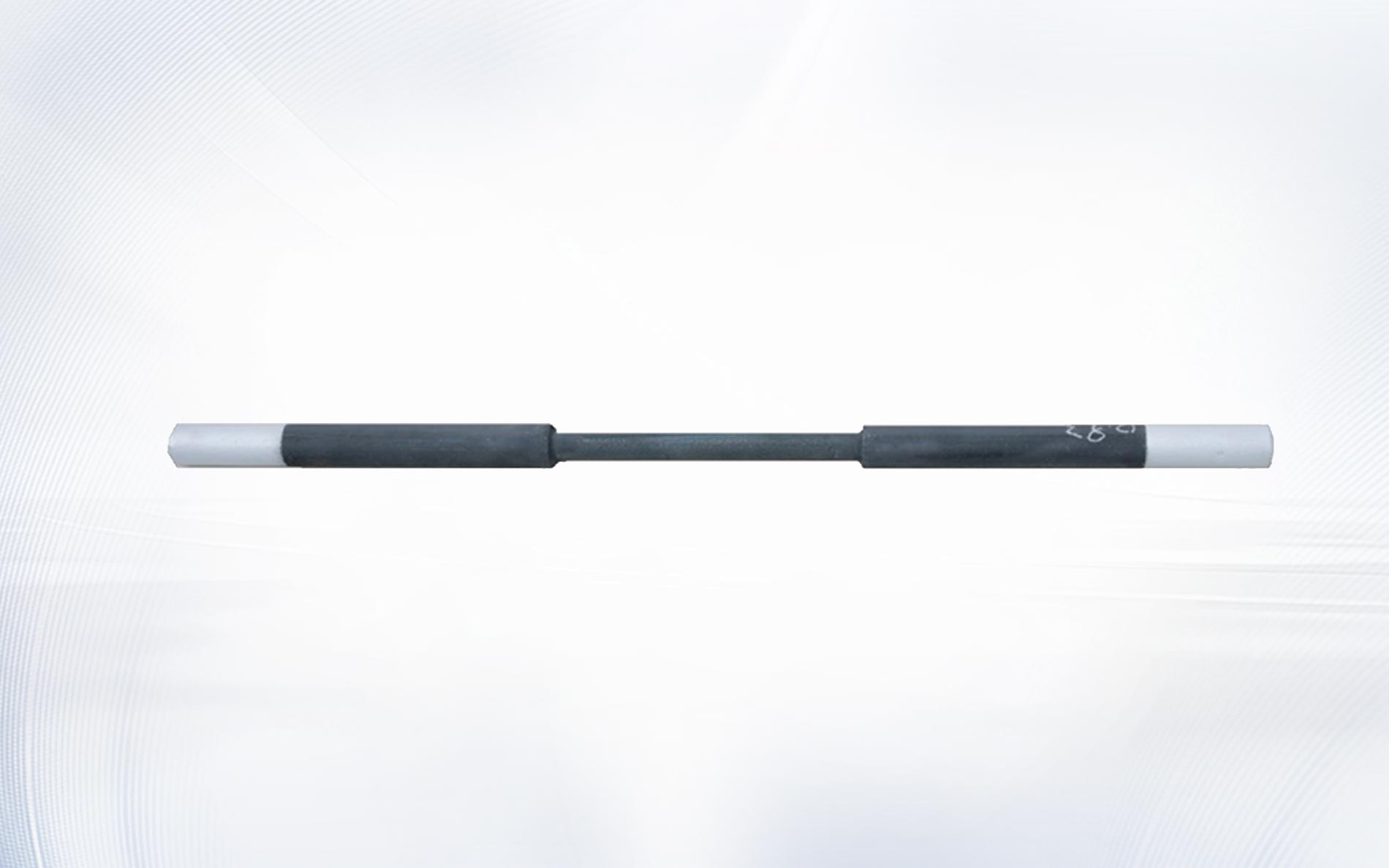
When the application permits a straight equal-diameter design, the DH type SiC heating element page illustrates one possible geometry. Other furnace layouts may call for a different form, so shape should be selected from the installation rather than from habit.
Check the furnace opening and support arrangement
Measure the refractory opening, sleeve or support details, casing thickness, and the available external clearance. The silicon carbide heating element cold end must pass through the assembly without being forced, while the complete installation still limits unwanted movement and avoids concentrated mechanical loading.
Do not assume that the old opening represents the approved design. Refractory repairs, deposits, distorted metalwork, and previous substitutions can change the observed dimensions. Photograph both penetrations and compare measurements at several points before defining the silicon carbide heating element cold end diameter and clearance.
The element is not a structural beam. Cable weight, rigid buswork, or a tight packing arrangement should not load the silicon carbide heating element cold end. The furnace designer must specify supports, seals, and clearances suitable for temperature, atmosphere, electrical isolation, and expansion.
Design the terminal connection around access and contact
A connection has to be installed and inspected with the furnace in its safe maintenance state. Leave enough accessible silicon carbide heating element cold end length for the specified strap and clamp without placing the joint against refractory, hot casing, or another conductor.
Specify the connection hardware as part of the replacement package. Qixiang Material lists aluminum conductive strips, G type conductive strips, and a heating rod clamp for compatible applications. The correct choice depends on element dimensions and the approved furnace design.
Show the terminal centreline and usable contact area rather than writing only “standard end.” A supplier reviewing the silicon carbide heating element cold end can then check whether the requested terminal arrangement matches the proposed element and accessories.
Keep mechanical dimensions separate from electrical matching
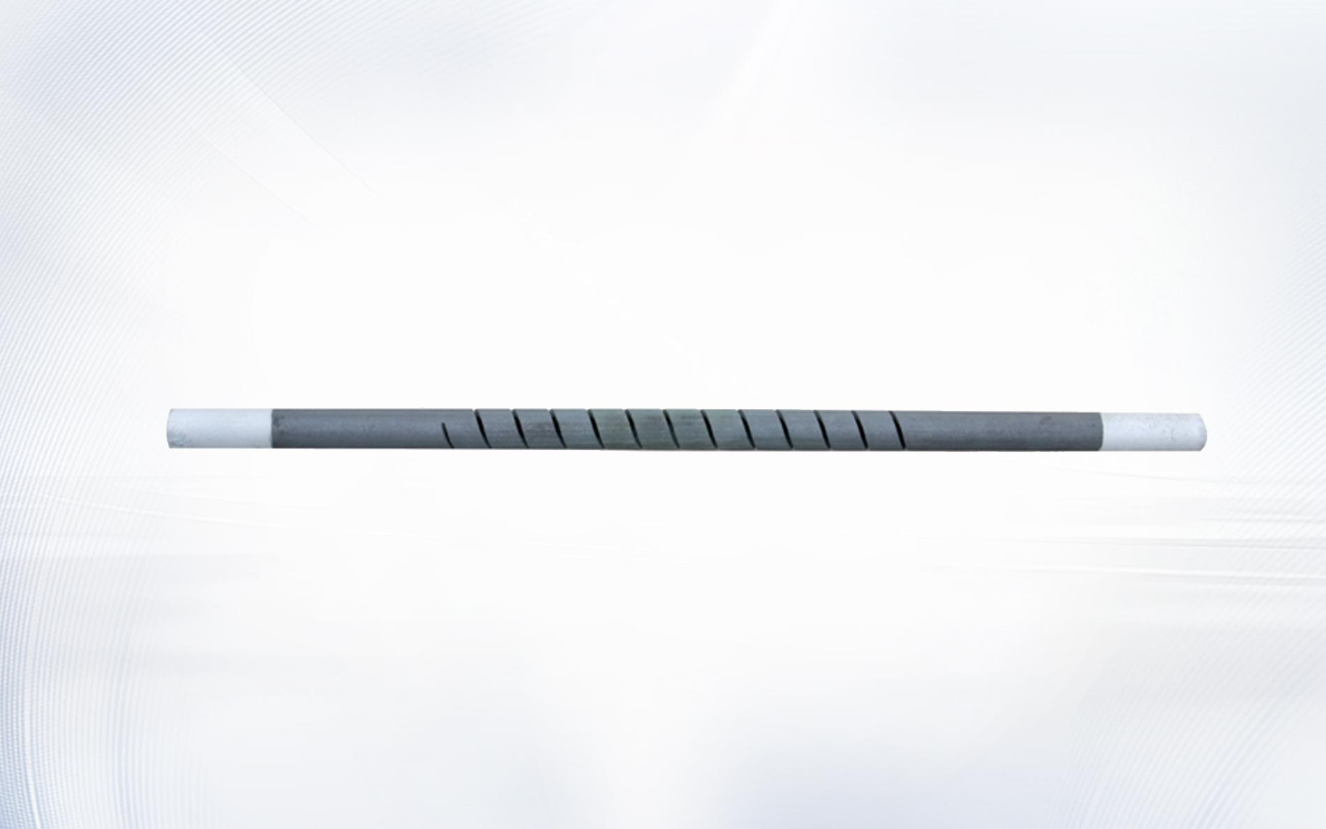
A perfect mechanical fit does not prove electrical compatibility. Resistance, design power, supply arrangement, transformer range, controller capacity, number of elements, and series or parallel grouping must be checked independently. The silicon carbide heating element cold end belongs on the dimensional drawing, while electrical values belong on the element data sheet and circuit schedule.
Record whether the resistance value describes one element, one branch, or the complete zone, and identify its reference condition. Do not infer resistance from silicon carbide heating element cold end length alone. Hot-zone geometry and the manufacturer’s element design are central to the electrical specification.
For basic unit relationships, see the NIST overview of electrical SI units. Qualified personnel must complete circuit calculations and approve the system. The silicon carbide heating element cold end measurement is only one input to a safe replacement decision.
Audit an old element without copying its damage
Before removal, label the furnace position and photograph the installed connection, support, penetration, and conductor route. After safe isolation, record the old element’s dimensions and condition. A cracked, eroded, contaminated, or previously shortened silicon carbide heating element cold end should not automatically become the master sample for a new order.
- Compare both ends rather than measuring the easier side only.
- Identify repair work or deposits that reduce the apparent opening.
- Note discolouration or local heating near the connection.
- Record terminal strap and clamp dimensions.
- Check the controlled drawing, purchase record, and electrical schedule for conflicts.
Use the evidence to create a new controlled specification. If records disagree, flag the uncertainty instead of averaging dimensions. NIST Technical Note 1297 explains the general importance of expressing measurement uncertainty; the project team should apply an appropriate dimensional inspection method to the silicon carbide heating element cold end.
Plan handling, identification, and receipt inspection
Long ceramic heating elements need suitable packaging and careful handling. Include part number, furnace position, dimensions, resistance reference, quantity, and orientation notes on the purchase and receiving documents. A silicon carbide heating element cold end can be damaged by impact or used as a lifting point even when the shipping carton appears intact.
At receipt, compare the product label and drawing, inspect visible condition, and measure the agreed characteristics using suitable tools. Keep the element supported according to the supplier’s instructions. OSHA’s warehousing safety resources provide general workplace handling considerations; site-specific procedures still govern the inspection of a silicon carbide heating element cold end.

Build a complete RFQ package
A useful request for quotation combines a dimensioned drawing with the electrical and operating context. State the silicon carbide heating element cold end length on each side, overall and hot-zone lengths, diameter, terminal details, element shape, resistance requirement and reference, circuit grouping, voltage range, chamber temperature, atmosphere, cycle, quantity, and required documentation.
Add photographs of the installed position, penetration, connection, and nameplate, but do not use photographs as a substitute for dimensions. If the replacement changes any silicon carbide heating element cold end detail, request a drawing review before production and have the responsible furnace and electrical engineers approve the change.
For equipment safety, isolation, and maintenance planning, consult the requirements applicable to the installation. In the United States, OSHA’s control of hazardous energy standard is relevant to servicing practices. The IEC 60519-1 overview describes the scope of general safety requirements for industrial electroheating installations.
Frequently asked questions
Can I order from overall length alone?
No. Overall length does not locate the hot zone, define the two end lengths, confirm diameter, or describe the terminal area. A silicon carbide heating element cold end needs a dimensioned drawing.
Do both cold ends have to be the same length?
Not always. Furnace walls, terminal boxes, access, and conductor arrangements can be asymmetric. Measure and label each silicon carbide heating element cold end rather than assuming symmetry.
Can a longer cold end fix an overheating terminal?
It should not be treated as an automatic fix. Contact condition, strap size, clamp, routing, current, wall temperature, support, and element specification all require review. Changing the silicon carbide heating element cold end is an engineering decision.
Should resistance be measured at the terminal ends?
Follow the manufacturer’s approved method and record the reference condition. Resistance verification and silicon carbide heating element cold end dimensional inspection are related acceptance tasks, but they are not the same measurement.
What should I send for a fast technical review?
Send the controlled drawing, photos, all key dimensions, resistance and circuit data, furnace temperature, atmosphere, cycle, quantity, and connection details. Clearly mark every silicon carbide heating element cold end dimension that is confirmed or uncertain.
Turn a sample into a controlled replacement specification
The safest purchasing shortcut is not a model nickname; it is a complete, reviewed drawing. By locating the hot zone, measuring both sides, checking the penetration, and documenting the terminal connection, a buyer can specify the silicon carbide heating element cold end in a form that engineering, procurement, production, and receiving can all verify.
Contact Qixiang Material with your drawing, photographs, operating data, and quantity for a technical discussion. The team can review element geometry and compatible connection accessories while your responsible engineers approve the furnace installation and electrical design.