A replacement heating rod can match the old rod’s total length and still be wrong for the furnace. The hot zone may sit partly inside the insulation, the cold ends may stop too close to the wall, the terminals may not fit the existing connectors, or the resistance may be incompatible with the rest of the heating zone.
That is why silicon carbide heating element dimensions should never be reduced to a single length and diameter. A reliable specification combines physical measurements, electrical data, element geometry, furnace construction, operating temperature, atmosphere, and connection requirements.
This guide explains how industrial buyers, furnace engineers, and maintenance teams can measure and document silicon carbide heating element dimensions before requesting a new element or planning a replacement. It also provides a practical RFQ worksheet that can help prevent costly specification errors.
Table of Contents
Key Points Before You Measure
- Do not order a replacement from overall length alone.
- Confirm the outer diameter, hot zone, cold zone, overall length, and resistance.
- Measure both cold ends when their lengths are not identical.
- Record center spacing and bridge dimensions for U-shaped and multi-leg elements.
- Identify the terminal style, conductive strip, clamp, and wiring direction.
- Provide furnace voltage, circuit arrangement, working temperature, and atmosphere.
- Measure resistance under a known and consistent temperature condition.
- Use an original drawing or nameplate when available, but verify it against the installed element.
Qixiang provides multiple silicon carbide heating elements for industrial furnaces, kilns, and laboratory heating equipment. The correct model can only be selected when the element data and furnace conditions are considered together.
Why Silicon Carbide Heating Element Dimensions Are System Data
A silicon carbide heating element is an electrical resistance heater made from silicon carbide material. Its active section converts electrical energy into heat, while lower-resistance terminal sections carry current through or near the furnace wall.
The element does not work independently. It operates as part of a system that includes the furnace chamber, insulation, supports, electrical circuit, temperature controller, terminals, process load, and furnace atmosphere. The U.S. Department of Energy similarly treats industrial process heating as a complete system rather than a collection of isolated parts.
For this reason, silicon carbide heating element dimensions influence much more than physical fit. They affect:
- The position of the heat inside the chamber
- Radiating surface area
- Element surface loading
- Terminal temperature
- Electrical resistance
- Furnace power distribution
- Mechanical clearance during expansion
- Connection accessibility
- Temperature uniformity
Two elements that look nearly identical can behave differently if their hot zone lengths or resistance values are not the same.
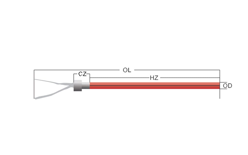
What Do OD, HZ, CZ, and OL Mean?
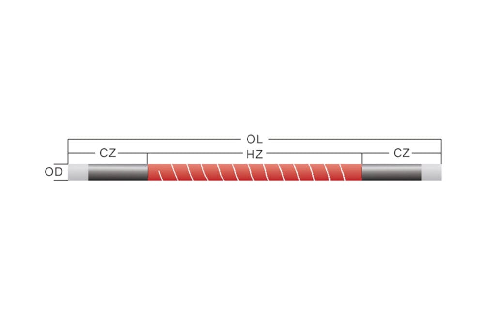
The most common silicon carbide heating element dimensions are identified as OD, HZ, CZ, and OL. These abbreviations should appear on the drawing, quotation, purchase order, and final inspection record.
| Abbreviation | Meaning | What to Measure | Why It Matters |
|---|---|---|---|
| OD | Outer Diameter | Diameter of the rod or tube | Affects furnace-hole fit, mechanical strength, surface area, and available resistance range |
| HZ | Hot Zone | Length of the active heating section | Determines where heat is generated and contributes to radiating area |
| CZ | Cold Zone or Cold End | Lower-resistance length outside the active section | Carries current through the wall while limiting unwanted terminal heating |
| OL | Overall Length | Total end-to-end length | Determines whether the element fits the complete installation span |
| R | Resistance | Specified resistance at an agreed reference condition | Influences current, power, grouping, and compatibility with the furnace circuit |
Outer Diameter
Outer diameter is not only a mechanical measurement. It also changes the radiating surface area and influences the resistance range that can be manufactured. A rod that is too large may bind in the furnace opening. One that is too small may not match the supports, seals, or terminal hardware.
When recording silicon carbide heating element dimensions, take diameter readings at several positions around the circumference and along the relevant section. Record the unit, measuring tool, nominal requirement, and actual reading instead of rounding an uncertain value.
For thickened-end designs, record both the hot-zone diameter and the cold-end diameter. The DB type silicon carbide heating element is an example of a structure where these diameters must be documented separately.
Hot Zone Length
The hot zone should align with the intended heating space. If part of the active section remains inside the furnace wall or insulation, heat can become concentrated where it is not wanted. If the hot zone is too short, the chamber may develop weak heating near the sides.
When checking silicon carbide heating element dimensions, identify the visible or marked transition between the active section and each cold end. Do not assume the darkest section always represents the complete hot zone, especially on an aged or contaminated element.
Cold Zone Length
Within a complete set of silicon carbide heating element dimensions, the cold zone should pass through the furnace wall and leave enough accessible terminal length for the selected clamp and conductive strip. A cold end that is too short can place the connection close to chamber radiation. An unnecessarily long cold end may create installation or enclosure problems.
Record CZ1 and CZ2 separately if the two ends are unequal. For a simple straight element with equal cold ends, the relationship may be written as:
OL = HZ + 2(CZ)
For unequal cold ends:
OL = HZ + CZ1 + CZ2
These relationships apply only when the drawing uses the same reference points. Terminal coatings, collars, or external connector assemblies may require additional dimensions.
Overall Length
Among silicon carbide heating element dimensions, overall length is the easiest value to measure and therefore the most commonly overused. It confirms whether the element can span the installation, but it does not show where the heat will be produced. OL should always be recorded together with HZ, CZ, OD, geometry, and resistance.
How Element Geometry Changes the Measurement Method
Different structures require different measurement points. A complete record of silicon carbide heating element dimensions must reflect the actual geometry rather than forcing every product into a straight-rod worksheet.
| Element Structure | Additional Measurements | Typical Selection Concern |
| Equal-diameter straight rod | OD, HZ, CZ1, CZ2, OL | Correct alignment of the active section with the chamber |
| Thickened-end straight rod | Hot-zone diameter, cold-end diameter, transition position | Furnace-hole size and reduced heating at the terminals |
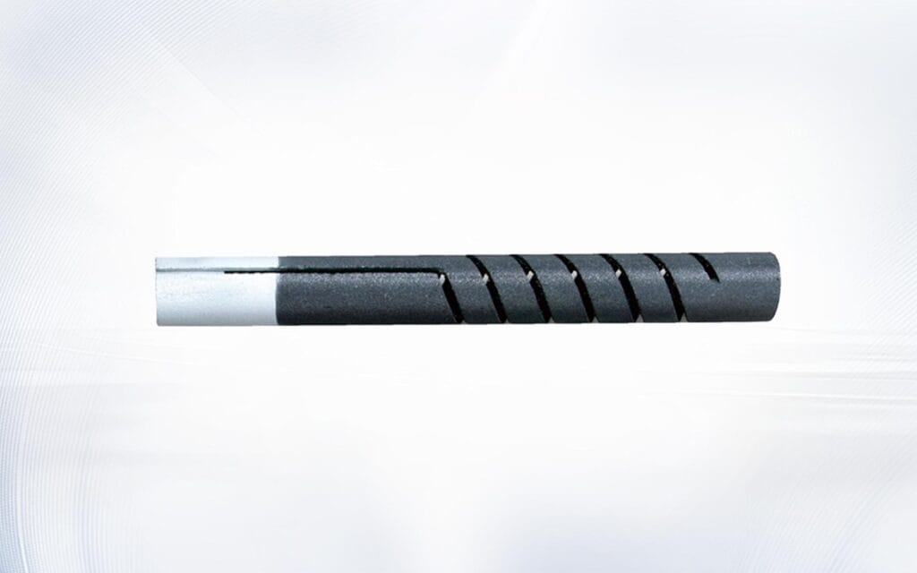
| Single-ended element | Tube diameter, slot or return-path dimensions, terminal length, sealed-end clearance | Both electrical connections are located on the same side |
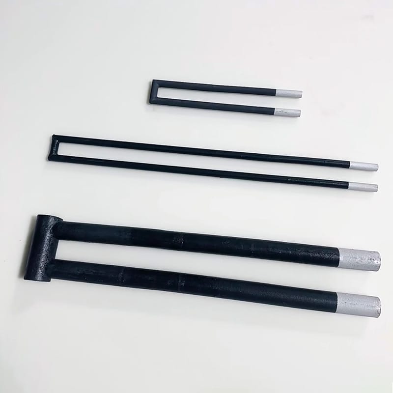
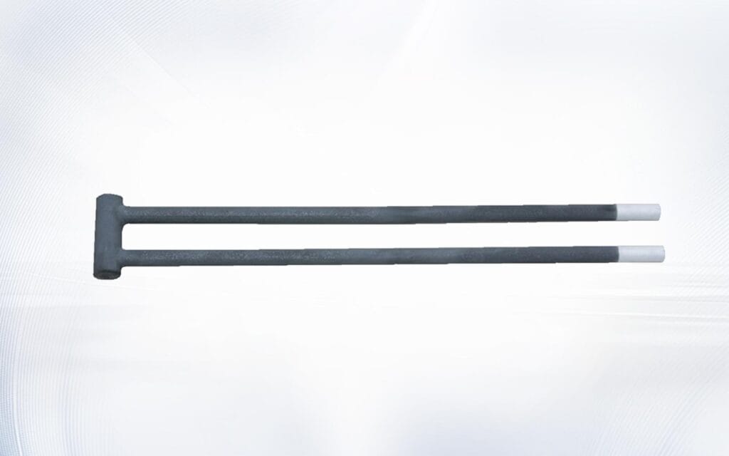
| U-shaped element | Leg length, center spacing, bridge diameter, bridge position | Furnace access, wiring side, and spacing between legs |
| W-shaped or multi-leg element | Number of legs, leg spacing, bridge dimensions, terminal layout | Phase arrangement and uniform coverage across a large zone |
Straight Equal-Diameter Elements
For a straight, equal-diameter structure such as the DH type SiC heating element, measure from consistent end faces and mark the beginning and end of the hot zone. These reference points make the specified silicon carbide heating element dimensions unambiguous. Confirm whether the cold ends are identical before using one CZ value for both sides.
Thickened-End Elements
For a thickened-end rod, record the smaller active-section diameter and the larger cold-end diameter. Also record the location and length of each transition. A correct OL with the wrong transition position can still place the hot zone inside the furnace lining.
Single-Ended Elements
Single-ended structures need more than OD and length. The buyer should document the terminal arrangement, wiring direction, active-section location, return path, closed-end clearance, and any collar or connector assembly. The UX type silicon carbide heating element illustrates why installation access and terminal structure must be considered alongside the specified silicon carbide heating element dimensions.
U-Shaped and Multi-Leg Elements
For a U-shaped silicon carbide rod, measure both legs rather than assuming they are identical. Record center-to-center spacing, bridge dimensions, terminal positions, and the direction in which the element enters the furnace.
For a W-shaped silicon carbide rod, include a front-view drawing. The number of legs, spacing, bridge geometry, and phase or circuit arrangement may all affect compatibility.
How to Measure an Existing Element Safely
Measurement should only begin after the furnace has been shut down, isolated, and cooled in accordance with the facility’s safety procedure. Electrical and thermal energy can remain hazardous even when the controller appears to be off. OSHA provides general guidance on the control of hazardous energy during equipment servicing.
Accurate silicon carbide heating element dimensions begin with a controlled measurement process. Do not collect data while the element is energized, hot, unsupported, or still connected to hardware that obscures the reference points.
Prepare the Measurement Tools
Useful tools may include:
- Calipers or an outside micrometer
- A steel rule or verified measuring tape
- A suitable resistance meter
- Identification labels
- A camera
- A printed measurement worksheet
- The furnace electrical drawing
- The previous purchase order or element specification
Record the Element Before Removal
Photograph the installed orientation, support points, terminal connections, conductive strips, clamps, furnace openings, and wiring direction. These images give essential context to the recorded silicon carbide heating element dimensions. Label every rod by furnace zone and position so similar-looking elements do not become mixed after removal.
Measure From Defined Reference Points
Write down exactly where each measurement begins and ends. For example, OL may be measured between ceramic body end faces, not between the ends of flexible connectors. Consistent reference points make silicon carbide heating element dimensions reproducible for the supplier and incoming inspection team.
Do Not Force a Damaged Element Straight
A cracked or broken rod should be supported while it is measured. Do not apply bending force to align fractured pieces. Measure each section separately and compare the combined result with the furnace span, original drawing, and neighboring elements.
Why Hot Zone Placement Matters More Than Total Length
In a schedule for silicon carbide heating element dimensions, HZ identifies the section designed to radiate most of the heat. Its position should correspond to the useful chamber area, not the furnace wall or external terminal enclosure.
If HZ is too long:
- The active section may enter the insulation
- Furnace openings may become overheated
- Terminal areas may run hotter
- Local material deterioration may accelerate
If HZ is too short:
- Heating near the chamber edges may weaken
- The process load may see uneven radiation
- The controller may compensate by increasing output
- Selected furnace zones may lag behind the setpoint
This is why silicon carbide heating element dimensions should be checked against a cross-section of the furnace wall. Record chamber width, insulation thickness, external terminal clearance, and the intended position of each hot-to-cold transition.
Resistance Is Part of the Dimensional Specification
Physical fit does not guarantee electrical compatibility. Resistance should appear beside silicon carbide heating element dimensions on every replacement drawing.
For a simplified resistive circuit:
P = V² / R
and
P = I²R
These relationships show why a resistance change affects current and power. Actual furnace behavior also depends on circuit arrangement, controller design, element temperature, and the resistance of other elements in the same zone.
To make silicon carbide heating element dimensions useful for electrical review, record:
- Original specified resistance, if available
- Measured resistance of each existing element
- Measurement temperature
- Meter and test method
- Required resistance tolerance
- Grouping requirements for each furnace zone
- Series, parallel, star, delta, or other circuit arrangement
Silicon carbide elements normally change resistance during service. The detailed silicon carbide heating element resistance guide explains why new and aged rods should not be grouped by appearance alone.
How Dimensions Affect Surface Loading
The diameter and hot zone determine the radiating surface area of a straight cylindrical heating section. For a basic straight hot zone:
Radiating Area = π × OD × HZ
If OD and HZ are expressed in centimeters, the area is obtained in square centimeters. Element surface loading can then be expressed as:
Surface Loading = Element Power / Radiating Area
This calculation explains why changing silicon carbide heating element dimensions without reviewing power can affect element surface temperature and service conditions. It also shows why the dimensions and target power belong on the same technical record. A shorter hot zone carrying the same power has less radiating area. A different diameter also changes the available area and may require a new resistance or power review.
Surface loading should not be selected from a universal number. The acceptable value depends on element material, furnace temperature, atmosphere, operating cycle, geometry, heat transfer, and required service life. Final loading should be confirmed by the furnace designer or element supplier.
Furnace Data Required With the Dimensions
A useful inquiry combines silicon carbide heating element dimensions with information about the furnace and process. This allows the supplier to check whether the requested element is physically and electrically reasonable.
Provide the following:
- Furnace type and application
- Normal working temperature
- Maximum operating temperature
- Furnace atmosphere
- Process material and possible vapors or dust
- Voltage and installed power
- Number of elements
- Number of elements per control zone
- Circuit arrangement
- Continuous or intermittent operation
- Heating and cooling cycle frequency
- Existing failure symptoms
- Required quantity and spare strategy
This operating context prevents silicon carbide heating element dimensions from being evaluated in isolation from the process they must serve.
Atmosphere is particularly important because oxygen level, moisture, reactive gases, and process contamination may influence element selection and aging. Review the furnace atmosphere and SiC heating elements guide before specifying replacements for a new process.
A Practical RFQ Worksheet
Use the following table to standardize silicon carbide heating element dimensions when requesting a quotation. Attach a marked drawing and clear photographs whenever possible.
| RFQ Field | Information to Provide |
| Element model or geometry | Straight, thickened-end, single-ended, U-shaped, W-shaped, or custom |
| OD | Hot-zone and cold-end diameters where different |
| HZ | Active heating length and transition reference points |
| CZ | CZ1 and CZ2, or each leg’s cold-end length |
| OL | End-to-end body length with reference points defined |
| Shaped-element dimensions | Center spacing, leg length, bridge dimensions, and terminal direction |
| Resistance | Required value, tolerance, and reference temperature |
| Electrical system | Voltage, power, current, circuit arrangement, and controller type |
| Furnace conditions | Working temperature, maximum temperature, atmosphere, and cycle |
| Installation | Horizontal or vertical, supports, furnace-hole size, and terminal clearance |
| Accessories | Clamp style, conductive strip size, terminal coating, and cable direction |
| Quantity | Installed quantity, quantity per zone, and spare quantity |
This worksheet makes silicon carbide heating element dimensions easier to verify before production and provides a shared record for purchasing, engineering, and quality inspection.
Common Specification Mistakes
Most errors in silicon carbide heating element dimensions come from incomplete reference points, assumptions about symmetry, or separating mechanical measurements from electrical requirements.
| Mistake | Possible Result | Better Approach |
| Sending only a photograph | Scale, hot zone, resistance, and terminal details remain unknown | Send a dimensioned drawing and furnace data |
| Ordering by OL only | Correct overall fit but incorrect heat position | Include HZ, CZ1, CZ2, and transition points |
| Assuming both cold ends are equal | The new hot zone may shift inside the chamber | Measure both ends separately |
| Ignoring resistance | Power imbalance or incompatibility within the zone | Provide resistance, tolerance, and circuit information |
| Copying dimensions from an unrelated rod | Similar appearance hides different electrical design | Match the original specification and furnace conditions |
| Measuring flexible straps as part of OL | Body length becomes inaccurate | Define whether OL covers the ceramic element body only |
| Mixing millimeters and inches | Conversion and manufacturing errors | Use one primary unit and show conversions clearly |
| Reusing damaged accessories automatically | Poor contact can overheat the new element | Inspect clamps and conductive strips with the rod |
Connection hardware should be checked at the same time as the element. The guide to SiC heating element terminals explains how loose or unsuitable contacts can create local overheating even when the rod itself is correctly specified.
What If the Original Element Is Broken or Unmarked?
A missing nameplate does not make replacement impossible, but it requires more evidence.
To reconstruct missing silicon carbide heating element dimensions, start by measuring the furnace:
- Chamber width at the element position
- Wall and insulation thickness
- Distance between furnace openings
- Hole diameter
- Support positions
- Terminal enclosure clearance
- Distance from the element to the process load
Then compare neighboring rods in the same zone. Record their dimensions, resistance, terminal structure, and installation direction. Review electrical drawings, controller settings, transformer information, old purchase records, maintenance photographs, and spare parts in storage.
Do not assume an intact neighboring rod is still the original specification. It may be an earlier replacement. The silicon carbide heating rod replacement guide provides additional checks for deciding whether one rod or an entire zone should be replaced.
Incoming Inspection Before Installation
The approved drawing should become the inspection standard when the elements arrive. Check silicon carbide heating element dimensions before the furnace shutdown begins.
An incoming inspection should confirm:
- Product model and quantity
- OD, HZ, CZ, OL, and shaped-element measurements
- Resistance and grouping labels
- Straightness and visible integrity
- Terminal coating and connector position
- Clamp and conductive-strip compatibility
- Packaging condition
- Identification of matched furnace zones
Do not install an element simply because it fits through the furnace opening. Compare the delivered silicon carbide heating element dimensions and electrical values with the approved order record. Early inspection allows discrepancies to be resolved before production downtime begins.
How to Build a Repeatable Replacement Record
The best time to document silicon carbide heating element dimensions is before an emergency failure. Create a controlled record for every furnace model and heating zone.
The record should include:
- Approved element drawing
- Original resistance and tolerance
- Installed position and zone number
- Installation date
- Supplier batch or traceability number
- Resistance measurements over time
- Terminal inspection photographs
- Furnace atmosphere and operating cycle
- Replacement reason
- Changes made during maintenance
This history helps maintenance teams distinguish accidental breakage from normal resistance aging, connection failure, atmosphere-related damage, or an incorrect previous replacement.
FAQ
What are the most important silicon carbide heating element dimensions?
The essential values are outer diameter, hot zone length, cold zone length, overall length, and resistance. Thickened-end, single-ended, U-shaped, and W-shaped elements also require geometry-specific measurements such as separate diameters, center spacing, leg length, bridge size, and terminal direction.
Can I order a replacement from the overall length and diameter?
Usually not. OL and OD do not identify the position of the hot zone, cold-end lengths, electrical resistance, terminal structure, or circuit compatibility. A complete specification of silicon carbide heating element dimensions is needed to reduce replacement risk.
Should resistance be measured when the element is hot or cold?
Use the reference condition specified by the manufacturer or furnace documentation. For comparison, every element should be measured under consistent conditions with a documented method. Do not compare a warm element with one measured at room temperature.
Why are the hot zone and cold zone different?
The hot zone is designed to generate most of the process heat. Cold ends provide a lower-resistance path through the furnace wall and toward the external connection. Their correct lengths help keep the active heat in the intended chamber area.
How do I measure a U-shaped silicon carbide element?
Measure each leg, hot and cold sections, outer diameter, overall insertion length, center-to-center spacing, bridge dimensions, and terminal orientation. Include a front-view and side-view drawing because a single length cannot describe the complete geometry.
What information should accompany silicon carbide heating element dimensions?
Provide furnace type, application, working and maximum temperatures, atmosphere, voltage, power, circuit arrangement, number of elements per zone, operating cycle, terminal accessories, and the reason for replacement.
Can new and old elements be used in the same furnace zone?
Sometimes, but compatibility should be evaluated from resistance, remaining element condition, circuit arrangement, and production requirements. A new rod with the correct physical size may still create imbalance when grouped with heavily aged elements.
Where can I request help checking a replacement drawing?
Send the drawing, photographs, furnace data, resistance information, and required quantity through the Qixiang contact page. The technical team can review the available information before a specification is confirmed.
Conclusion
Accurate silicon carbide heating element dimensions are the foundation of a reliable replacement, but dimensional accuracy alone is not enough. OD, HZ, CZ, and OL must be evaluated together with resistance, geometry, circuit design, furnace wall construction, atmosphere, operating temperature, and terminal hardware.
The most effective purchasing process uses a dimensioned drawing, a complete furnace data sheet, resistance records, installation photographs, and a documented inspection plan. This approach reduces ambiguity, keeps the active heat in the correct location, and makes it easier to match the new element with the existing furnace system.
Before placing an order, verify the silicon carbide heating element dimensions, electrical requirements, and operating conditions as one complete specification. That is the difference between an element that merely fits and one that is properly selected for the furnace.