Heating elements are often selected too early in a furnace project. A catalog resistance or nominal wattage may look convenient, but it cannot replace a heat-duty model, a zone plan, and an electrical operating window. A reliable silicon carbide heating element power calculation starts with the process: what must be heated, how quickly it must be heated, and how much energy the furnace loses while doing it.
This guide is written for furnace engineers, equipment builders, maintenance teams, and technical buyers who need a calculation they can review and commission. It explains how to move from total furnace duty to per-element voltage and current without confusing chamber load, zone load, branch load, and individual-element load.
Define the calculation boundary before using a formula
The first decision in a silicon carbide heating element power calculation is the boundary. Are you sizing the whole furnace, one independently controlled zone, one electrical branch, or one element? Write that boundary at the top of the worksheet. It prevents a common error: dividing total furnace kilowatts by the number of elements even though different zones have different losses or different installed quantities. This boundary also makes the silicon carbide heating element power calculation reviewable by mechanical, process, and electrical teams.
- For the furnace boundary, record total product load, fixtures, refractory, openings, exhaust, and target heat-up time.
- For each zone, record its specific wall area, door or end losses, element count, sensor location, and control method.
- For each branch, record the series/parallel arrangement, transformer secondary voltage, current limit, and protective devices.
- For each element, use resistance at a stated reference condition and the supplier’s permitted operating range.
The U.S. Department of Energy’s overview of process heat basics is a useful reminder that the heating system includes the heat source, enclosure, material handling, controls, and load. A silicon carbide heating element power calculation should therefore be reviewed as a system calculation, not as a rod-only calculation.
Build heat duty from energy and losses
Start the silicon carbide heating element power calculation with the energy required to raise the product, trays, fixtures, and relevant refractory mass from the starting temperature to the process temperature. For each material, the basic relationship is mass multiplied by average specific heat multiplied by temperature rise. Where specific heat changes materially with temperature, use temperature-dependent data or divide the range into intervals rather than relying on a single room-temperature value.
Next, convert that energy into average warm-up power by dividing it by the allowed heat-up time. Then add estimated wall, door, opening, exhaust, cooling-water, and air-infiltration losses. This stage of silicon carbide heating element power calculation should keep calculated energy separate from estimated losses. It makes later commissioning much easier because the team can see which assumption needs correction if the measured warm-up differs from the model. Keep each loss assumption visible in the silicon carbide heating element power calculation instead of burying it in a single efficiency factor.
Do not assume that warm-up duty and holding duty are the same. Warm-up power must heat stored mass as well as replace losses. Holding power mainly replaces continuing losses and process extraction. DOE’s process heating technical publications provide broader guidance for assessing industrial heating systems and loss-reduction opportunities.
Allocate total power by thermal zone
A chamber with equal physical zones rarely has equal thermal loads. The loading door, end walls, penetrations, exhaust path, conveyor entrance, and cooler adjacent equipment can create local losses. Good silicon carbide heating element power calculation practice allocates power according to those losses and the required temperature profile, then checks whether the available element positions can deliver that distribution.
Prepare a zone table with target kilowatts, element quantity, branch arrangement, installed kilowatts, sensor position, and expected controller output at steady state. If a zone routinely needs much more output than its neighbors, the cause may be insufficient installed capacity, but it may also be air leakage, damaged insulation, misplaced sensing, an imbalanced load, or a weak branch. The silicon carbide heating element power calculation should not hide those alternatives.
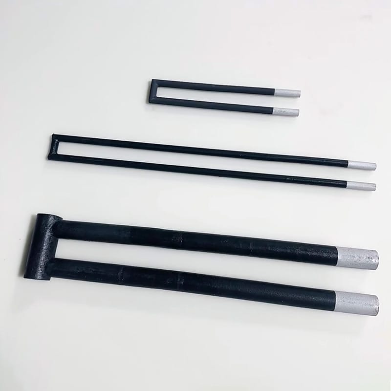
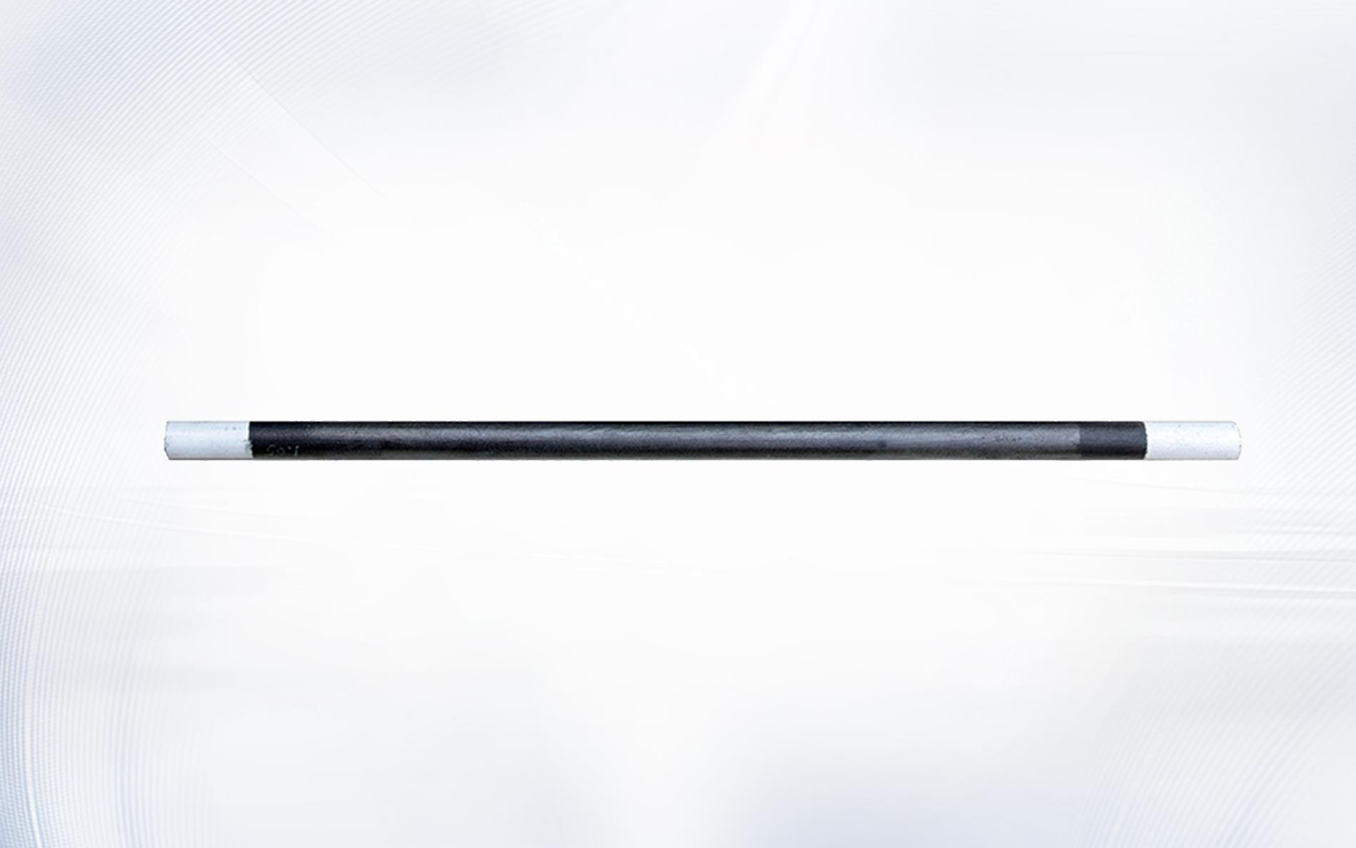
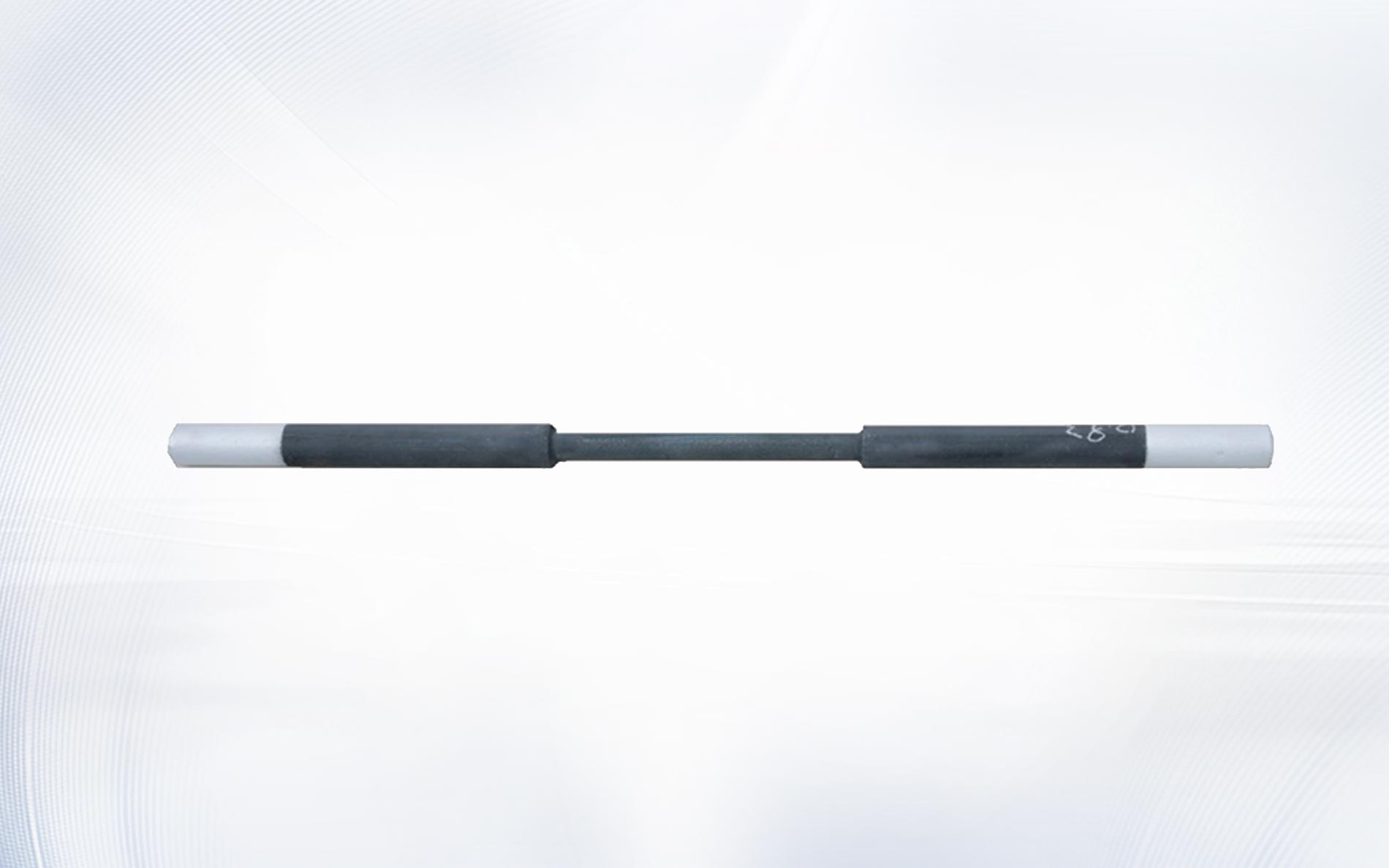
Element geometry also affects the layout. Review the DH type SiC heating element for a straight equal-diameter arrangement, the DB type silicon carbide heating element where that form suits the furnace construction, and other geometries only after the hot-zone length, cold ends, openings, and support conditions are defined.
Convert zone kilowatts into per-element load
Once the required power for a zone is known, divide it by the number of active elements in that zone to obtain the target power per element. That number is a design target, not an automatic approval. The silicon carbide heating element power calculation must also confirm that the resulting surface loading, element temperature, atmosphere, mounting, and life expectations are compatible with the selected element. Record the active heating length and diameter beside the silicon carbide heating element power calculation so the surface-area check uses the selected geometry.
For a resistive load, use the relationships P = V × I, P = I²R, and P = V²/R. Keep the units explicit: watts, volts, amperes, and ohms. Use resistance for the condition defined by the element supplier; do not silently combine a room-temperature measurement with a hot operating assumption. When comparing material-property information, the NIST Ceramics Data Portal entry for silicon carbide is an authoritative reference, but the purchased element’s electrical specification must govern the project calculation.
| Calculation level | Primary input | Output to verify | Typical mistake |
|---|---|---|---|
| Furnace | Process energy plus losses | Total required kW | Using nameplate power as heat duty |
| Zone | Local loss and process share | Zone kW | Dividing power equally without a loss model |
| Branch | Series/parallel arrangement | Branch voltage and current | Mixing branch resistance with element resistance |
| Element | Specified resistance and target watts | Element voltage, current, and surface load | Ignoring tolerance and resistance growth |
Check series and parallel circuit grouping
Electrical grouping changes the voltage and current seen by the transformer and controller. In a series string, resistances add and the same current passes through each element. In parallel, each branch sees the supply voltage and branch currents add. A silicon carbide heating element power calculation must show the resistance of one element, one series string, one parallel group, and the full zone separately. Keep the silicon carbide heating element power calculation aligned with the latest single-line diagram.
Group elements with compatible resistance so one position is not persistently under- or over-powered. Document the intended replacement grouping as well; a mathematically correct original design can become unbalanced when maintenance mixes substantially different resistance values. Show the approved groups directly on the silicon carbide heating element power calculation and the circuit drawing. Conductor, terminal, contactor, thyristor, fuse, and transformer selection must be completed by qualified electrical personnel under the applicable local rules. OSHA’s electrical standards overview is a useful safety reference for U.S. workplaces, but it does not replace project-specific engineering.

Reserve voltage range for resistance growth
Silicon carbide elements change resistance during service, so the initial operating point cannot consume the transformer’s entire usable secondary-voltage range. A practical silicon carbide heating element power calculation includes at least two operating points: the new-element condition and a defined higher-resistance condition supplied or approved for the application.
For the same target power, the required voltage rises with the square root of resistance, while current falls with the square root of resistance. That relationship helps define transformer taps or a variable secondary range. It does not justify an arbitrary aging factor. Use supplier data, the site’s recorded resistance trend, the process atmosphere, and the control strategy to set the review condition in the silicon carbide heating element power calculation.
The silicon carbide heating element power calculation should also test the opposite limit. New elements at the lowest resistance must not force current above the controller, transformer, conductor, or protection limits. A design with adequate aged-element voltage but excessive new-element current is not balanced.
Work through an illustrative zone example
Consider a hypothetical zone requiring 24 kW, fitted with six identical elements arranged as three parallel branches with two elements in series per branch. The target is 4 kW per element. If the stated design resistance is 2.0 Ω per element, one series branch is 4.0 Ω. Delivering 8 kW to that branch requires about 179 V and 44.7 A. Three branches draw about 134 A in total. These rounded values illustrate a silicon carbide heating element power calculation; they are not a product rating or a recommendation for a particular furnace.
Repeat the silicon carbide heating element power calculation using the highest approved review resistance, the minimum and maximum available secondary voltages, and the controller’s continuous-current rating. Then calculate the element’s active surface area and compare the resulting watt density with the supplier’s application guidance. If the voltage range, current limit, surface load, or terminal environment fails, change the element count, resistance selection, circuit grouping, or zone target before release.
Match element shape to the electrical and mechanical plan
The calculation and mechanical drawing must describe the same element. Hot-zone length determines where heat is released; cold-end length affects the furnace-wall transition and terminal temperature; diameter influences resistance, surface area, stiffness, and opening size. The silicon carbide heating element power calculation is incomplete until those dimensions are tied to a specific installation drawing. Use one controlled drawing revision for both the RFQ and the silicon carbide heating element power calculation.
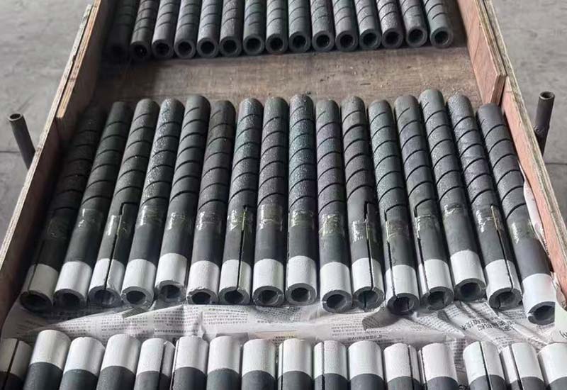
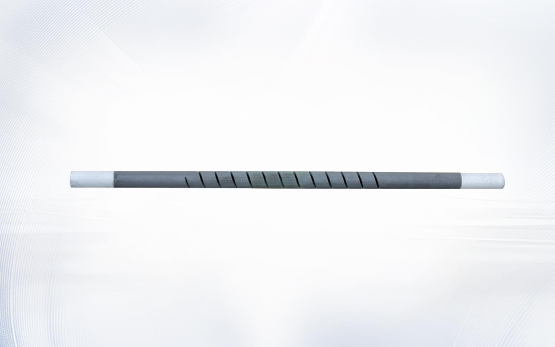
For alternative layouts, compare the SG type silicon carbide rod and UX type silicon carbide heating element. Selection should follow the furnace’s space, terminal access, support, power density, and replacement method rather than the appearance of the element alone.
Commission the model against measured operation
Before first heat, record element resistance, grouping, insulation resistance where applicable, transformer tap, controller limits, conductor size, protection settings, and terminal torque according to approved procedures. During staged energization, compare voltage and current by branch. The measured values should reconcile with the silicon carbide heating element power calculation within the tolerances defined by the responsible engineer.
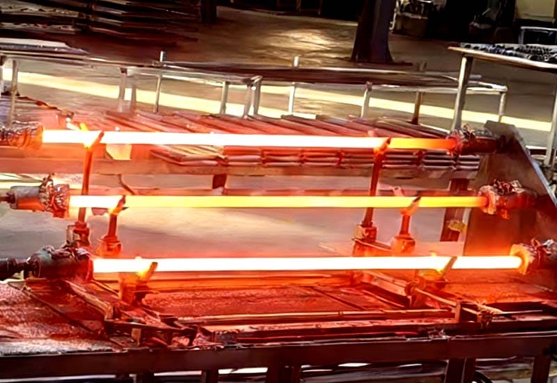
During warm-up and a representative production cycle, trend zone temperature, controller output, branch current, and relevant process events such as door opening or exhaust changes. Compare those trends with the silicon carbide heating element power calculation. If the furnace reaches temperature but one zone stays near maximum output, investigate heat loss, sensing, airflow, load distribution, connections, and element resistance before simply increasing installed power.
Update the silicon carbide heating element power calculation with as-built measurements and keep that revision with the furnace electrical drawings. It becomes the baseline for replacement decisions, resistance matching, transformer-tap changes, and later energy reviews.
Frequently asked questions
What information is required before calculating SiC element power?
A complete silicon carbide heating element power calculation needs process mass, temperature range, heat-up time, furnace losses, zone layout, element quantity, circuit arrangement, resistance condition, available voltage range, and current limits. Atmosphere, element dimensions, and mounting conditions are also required for the final selection check.
Should installed power equal calculated steady-state heat loss?
Usually not. Steady-state heat loss describes holding duty, while installed power may also need to satisfy warm-up time, process extraction, recovery, control authority, and credible operating variation. The silicon carbide heating element power calculation should justify the required margin through the duty model rather than a generic percentage.
Can room-temperature resistance be used directly?
Only when the specification defines how that value relates to the intended operating calculation. A silicon carbide heating element power calculation must state the resistance reference condition and use supplier-approved data for voltage, current, and aging checks. Record the measuring method beside the silicon carbide heating element power calculation.
Why calculate both new and aged operating points?
The new condition can produce the highest current, while a higher-resistance condition can demand the highest voltage for the same power. Checking both in the silicon carbide heating element power calculation helps define a transformer and controller range that remains usable through the planned service interval.
What should be included in an RFQ?
Send the element drawing, hot- and cold-zone dimensions, resistance requirement and reference condition, quantity, circuit diagram, transformer range, furnace temperature, atmosphere, duty cycle, mounting orientation, terminal details, and the relevant silicon carbide heating element power calculation. Clear operating data reduces avoidable back-and-forth.
Turn the calculation into a reviewable engineering package
A useful result is not a single wattage. The silicon carbide heating element power calculation is a traceable package that connects heat duty, zone allocation, element geometry, resistance, circuit grouping, transformer range, controls, and commissioning measurements. That package lets procurement compare like with like and gives maintenance a defensible baseline.
For a new furnace or a replacement review, contact Qixiang Material with the furnace conditions, drawings, electrical limits, current element information, and silicon carbide heating element power calculation. The team can discuss a suitable element configuration while your responsible furnace and electrical engineers approve the complete system design.