A slow furnace does not automatically need new elements. A changed load, damaged insulation, open door, poor connection, incorrect transformer tap, sensor error, or atmosphere upset can produce the same symptom. The decision to replace silicon carbide heating elements should follow electrical, mechanical, thermal, and process evidence rather than one controller reading.
This guide explains eight warning signs that can justify a plan to replace silicon carbide heating elements, plus the checks that prevent unnecessary replacement. It also shows when one element, a matched string, or a larger group may need review.
Check the furnace before condemning the elements
Compare the current process with the last known healthy condition. Record load mass and arrangement, target temperature, atmosphere, door or conveyor events, controller output, transformer tap, secondary voltage, branch current, resistance, insulation condition, and sensor status. Do not replace silicon carbide heating elements until the investigation separates increased furnace duty from reduced element capability.
- Verify that the production load and recipe have not changed.
- Inspect doors, seals, insulation, penetrations, and exhaust conditions.
- Check sensor calibration, location, and response.
- Compare voltage and current by branch at the same controller state.
- Inspect terminal straps, clamps, and conductor routing.
- Confirm the as-built circuit and transformer tap.
The U.S. Department of Energy’s process heating resources support a systems approach. That perspective helps a team decide whether to repair the furnace, correct the process, or replace silicon carbide heating elements.
Warning sign 1: an element is open or visibly fractured
An open circuit, complete fracture, or missing hot-zone section is a direct reason to isolate the affected circuit and review replacement. Before removal, photograph the break, supports, wall passage, terminals, deposits, and neighbouring elements. When teams replace silicon carbide heating elements without preserving evidence, the original cause is often lost.
Do not assume the fracture proves normal wear. Handling impact, tight openings, conductor load, thermal shock, surface overload, atmosphere effects, and resistance mismatch require different corrective actions. Complete that review before you replace silicon carbide heating elements or install a new part.
Warning sign 2: required power is unavailable within the approved voltage range
As resistance increases in service, more voltage is required to deliver the same power. Replacement becomes credible when a healthy, correctly connected branch cannot deliver required duty within the approved transformer and controller range. The decision to replace silicon carbide heating elements should use measured resistance, voltage, current, output, load, and recovery data from comparable conditions.
Confirm that the controller is actually commanding the expected output and that the transformer tap matches the drawing. Check conductors and connections for voltage drop. The SiC voltage control guide explains how new-element and later-life voltage windows should be documented.
Do not raise voltage beyond approved electrical or element limits to delay a necessary decision to replace silicon carbide heating elements. Higher voltage can overdrive healthy branches or hide a furnace-loss problem.
Warning sign 3: resistance mismatch can no longer be grouped safely
Series elements share current, but their voltage and power divide according to resistance. Parallel branches share voltage, while their currents differ with resistance. If available elements cannot be grouped within the approved matching range, it may be time to replace silicon carbide heating elements as a string or zone group rather than one at a time.
Measure resistance using the specified method and reference condition. Mark each element position and compare actual grouping with the as-built wiring diagram. Do not average unrelated room-temperature values or use dimensions as a substitute for resistance data when you replace silicon carbide heating elements.
The NIST electrical SI units overview helps keep volts, amperes, watts, and ohms consistent. Clear boundaries matter when calculating whether to regroup or replace silicon carbide heating elements.
Warning sign 4: the hot zone or cold end fails physical inspection
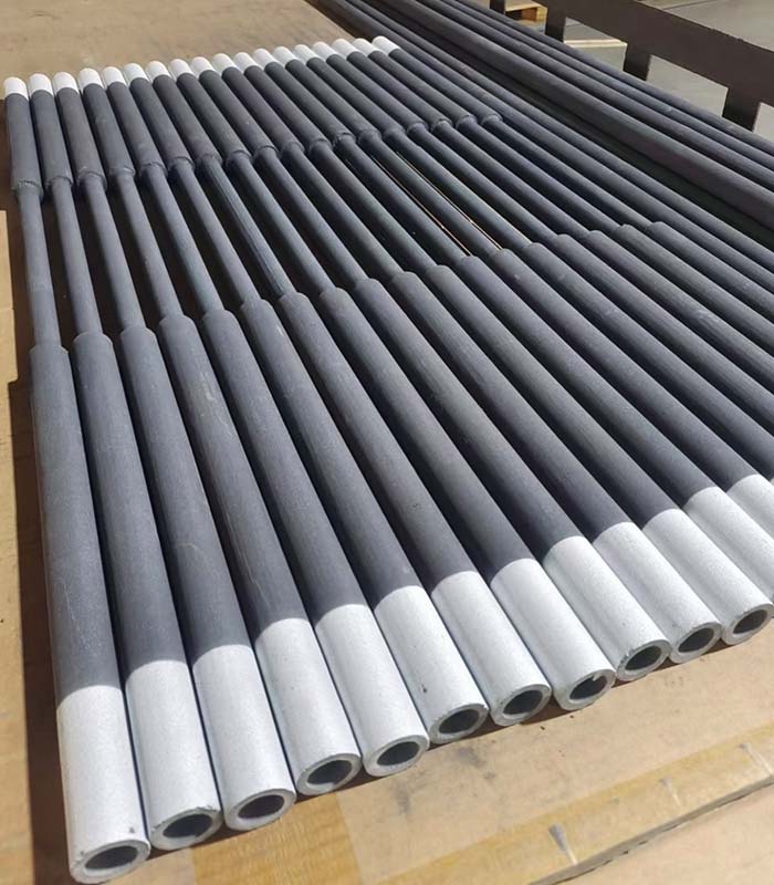
Cracks, severe local section loss, damaged transitions, distorted geometry, contaminated surfaces outside the approved condition, or a compromised terminal section can make continued operation unsuitable. Establish visual and dimensional acceptance criteria before deciding to replace silicon carbide heating elements.
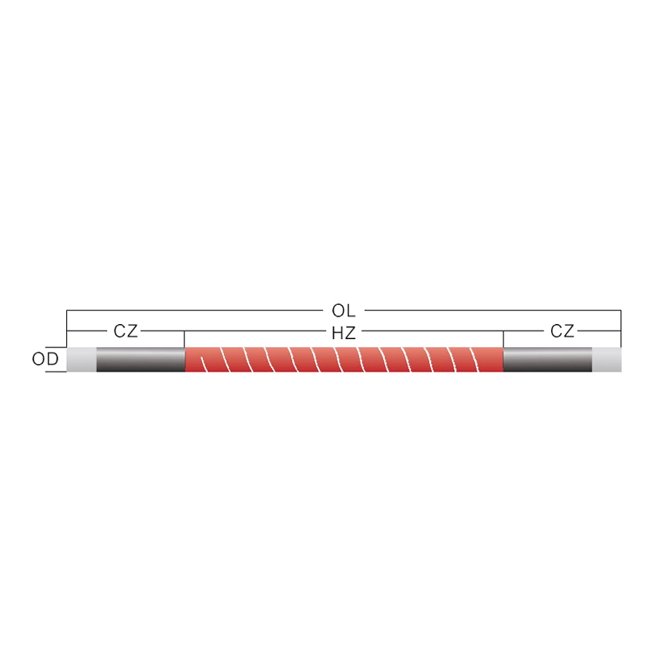
Compare the installed part with its controlled drawing. Measure overall length, hot-zone length, both cold ends, diameter, terminal area, and furnace opening. Check every confirmed dimension before you replace silicon carbide heating elements or release a new order.
A surface colour change alone is not enough. Combine inspection with resistance, atmosphere, temperature, deposit, and electrical evidence before approving a plan to replace silicon carbide heating elements.
Warning sign 5: repeated branch imbalance affects process performance
A branch that consistently draws less or more current than peers can create uneven zone power. First verify voltage, circuit grouping, resistance, connections, controller state, and measurement method. If unacceptable imbalance remains because element resistance cannot be matched, the responsible team may need to replace silicon carbide heating elements in the affected group.
Compare branches at the same temperature, tap, load, and output. The SiC current calculation guide shows how to move from element and branch resistance to total secondary current.
Do not use total zone current alone. Two different branch distributions can produce a similar total, so a decision to replace silicon carbide heating elements needs position-level data.
| Condition | Check before replacement | Likely replacement scope |
|---|---|---|
| One open element in a series string | Cause, resistance of remaining elements, voltage range | One element or matched string, per approved strategy |
| Several aged branches near voltage limit | Furnace loss, load, tap, controller, resistance trend | Selected matched groups or complete zone |
| One hot terminal | Strap, clamp, contact, conductor support, current | Connection repair unless the element terminal is damaged |
| Uneven load temperature | Sensors, placement, shielding, airflow, branch power | Only affected groups after diagnosis |
| New process or atmosphere | Compatibility, surface loading, geometry, controls | Engineering review may require a new specification |
Warning sign 6: terminal damage extends into the element
A loose strap or clamp may be repairable when the element terminal remains within acceptance criteria. Replacement is more likely when arcing, local overheating, cracking, or material loss has damaged the cold end or usable contact area. Inspect safely before deciding to replace silicon carbide heating elements.
Check compatible aluminum conductive strips, G type strips, and heating rod clamps. Correct conductor support and connection practice before the new element is installed.
For U.S. servicing work, OSHA’s control of hazardous energy standard is relevant alongside site procedures. Safe isolation is required before teams inspect or replace silicon carbide heating elements.
Warning sign 7: a process change moves operation outside the approved envelope
A higher temperature, different atmosphere, heavier load, shorter cycle, changed fixture, or new furnace pressure can make the previous element specification unsuitable. Engineering may need to replace silicon carbide heating elements even when the existing parts have not failed electrically.
Recalculate zone duty, watts per element, surface loading, resistance, voltage, current, and element placement. Review hot-zone and cold-end geometry against the changed load. Do not assume that adding elements or selecting a thicker rod automatically solves the process requirement.
The change review should define whether the furnace, transformer, controller, openings, supports, and connections remain suitable. The IEC 60519-1 overview describes the scope of general safety requirements for industrial electroheating installations; applicable standards and project engineering govern any plan to replace silicon carbide heating elements.
Warning sign 8: failures repeat in the same position after correct installation
Repeated failure at one location indicates a local condition that must be found before another replacement. Check opening alignment, support, wall temperature, gas flow, load radiation, deposits, element power, sensor position, and connection load. Do not repeatedly replace silicon carbide heating elements while leaving the same cause in place.
Compare the failed position with an unaffected position under the same cycle. Photograph both and retain voltage, current, resistance, temperature, and atmosphere data. Correct the furnace or process condition, then define how the next installation will verify the change.
Choose the replacement scope
The choice between one element, one series string, selected resistance groups, or a complete zone depends on the circuit, resistance distribution, service history, available voltage range, process impact, and approved maintenance strategy. Use data to decide how broadly to replace silicon carbide heating elements.
Replacing one part may be practical in an independently controlled position with compatible resistance. In a series string, a new element of substantially different resistance can redistribute voltage and power. In a heavily aged zone, repeated single replacements may consume downtime without restoring a stable grouping.
Document removed resistance, position, cause, new resistance, grouping, tap, and baseline current after work. That history improves the next decision to replace silicon carbide heating elements.
Build a replacement RFQ that prevents another mismatch
Send a controlled drawing with overall length, hot zone, both cold ends, diameter, terminal details, shape, resistance and reference condition, tolerance or matching requirement, quantity, and furnace position. Add the series-parallel circuit, transformer secondary range, power, temperature, atmosphere, cycle, load, service history, and failure evidence.
State whether you intend to replace silicon carbide heating elements individually, by string, or by zone so the resistance and quantity discussion matches the maintenance plan. Photos support the drawing but do not replace dimensions.
Frequently asked questions
Does slow furnace heating mean the elements are worn out?
Not necessarily. Check load, insulation, doors, sensors, voltage, current, connections, tap, and atmosphere before deciding to replace silicon carbide heating elements.
Can only one failed element be replaced?
Sometimes, but the circuit and resistance-matching strategy decide. When you replace silicon carbide heating elements in series strings or heavily aged groups, broader replacement may be needed to maintain power balance.
Is high controller output a replacement signal?
It is a warning, not proof. Compare the same load and temperature with resistance, voltage, current, tap, losses, and sensor data.
Should all elements in a zone be replaced together?
Only when resistance distribution, service history, circuit design, downtime, or process requirements justify it. Use an approved grouping and replacement plan.
What data helps a supplier recommend replacements?
Provide drawings, resistance and grouping, voltage and current, transformer range, temperature, atmosphere, cycle, load, installation and terminal photos, failure evidence, service history, and required quantity.
Use evidence to replace the right scope
The strongest replacement decision identifies both the failed capability and its cause. Verify the furnace, measure each branch, inspect the installation, compare the operating envelope, and select a compatible resistance group. This approach helps teams replace silicon carbide heating elements without repeating an avoidable outage.
For a replacement review, contact Qixiang Material with the controlled drawing, resistance history, circuit, electrical measurements, furnace temperature, atmosphere, cycle, load, photos, and quantity. The team can discuss suitable SiC elements and accessories while the responsible engineers approve the complete corrective action.