Un concepto de cableado de horno puede parecer simple en el papel: conectar varios elementos resistivos a un transformador y controlar la salida, pero una suposición incorrecta sobre resistencia, voltaje o agrupación puede producir potencia desigual, corriente excesiva o ninguna reserva de voltaje útil a medida que los elementos envejecen. Por lo tanto, un buen diagrama de cableado de elementos calefactores de SiC debe mostrar más que líneas entre terminales.
Esta guía explica cómo leer y preparar un diagrama de cableado de elementos calefactores de SiC para zonas de hornos en serie, paralelo y en serie-paralelo. Está destinado a diseñadores de equipos, ingenieros de mantenimiento y compradores técnicos que necesitan comunicar claramente los requisitos del circuito. El diseño final, la protección, la instalación y el trabajo energizado deben ser realizados por personal calificado según las normas y reglamentos aplicables al sitio.
Defina el límite eléctrico que se muestra en el diagrama
Comience nombrando el límite del diagrama de cableado del elemento calefactor de SiC. Un horno completo puede contener varias zonas controladas independientemente, y cada zona puede contener varias ramas. El dibujo debe distinguir el suministro entrante, la protección primaria, el transformador, el controlador de potencia, la conmutación de zona, la protección de rama cuando se utilice, los elementos, los terminales y las disposiciones de conexión a tierra o unión.
- Identifique el horno y el número de zona.
- Indique el sistema de suministro, la frecuencia y la conexión primaria del transformador.
- Mostrar el rango de tensión secundaria o grifos disponibles en la zona.
- Numere cada rama y cada posición de elemento.
- Registre la condición de referencia de resistencia utilizada para los cálculos.
- Marque los detalles aprobados del conductor, terminal, protección y aislamiento.
El Descripción general del NIST de unidades eléctricas SI proporciona las relaciones unitarias para amperios, voltios, vatios y ohmios. Utilice esos símbolos de forma coherente en el diagrama de cableado del elemento calefactor de SiC para que un revisor pueda rastrear cada cálculo de potencia y corriente.
Comprenda un elemento antes de agrupar varios
Para un elemento resistivo, las relaciones centrales son P = V × I, V = I × R, P = I²R y P = V²/R. Cada valor debe describir el mismo límite eléctrico. Si la resistencia es para un elemento, el voltaje y la corriente también deben ser para ese elemento. Mezclar la resistencia de las ramas con el voltaje por elemento es una fuente frecuente de errores en un diagrama de cableado del elemento calefactor de SiC.
Utilice la resistencia especificada para la condición relevante. La resistencia de los elementos de carburo de silicio cambia con la temperatura y el historial de servicio, por lo que la nota de dibujo o cálculo no debe decir simplemente “R” sin identificar la base. Un diagrama de cableado útil del elemento calefactor de SiC incluye tanto la resistencia de diseño como la agrupación de resistencia o tolerancia requerida para la instalación.
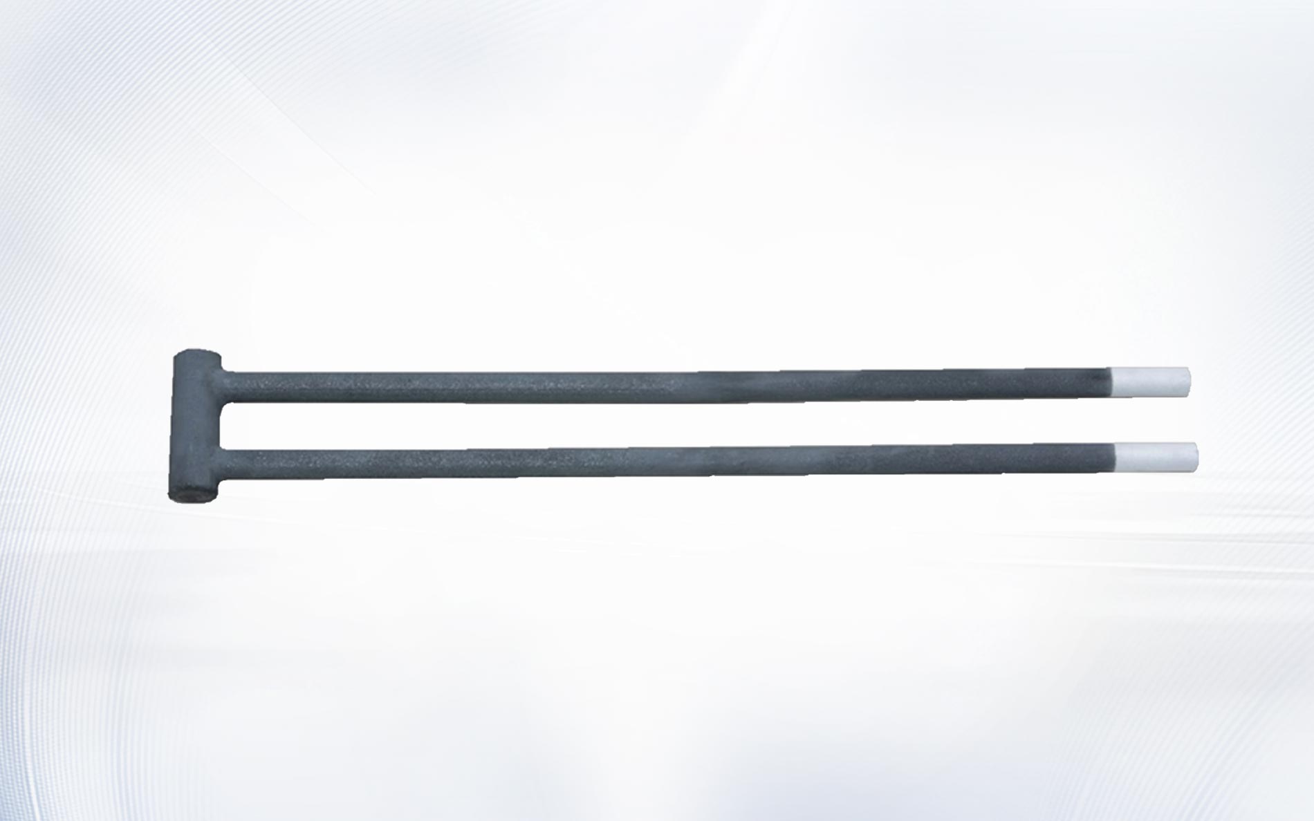
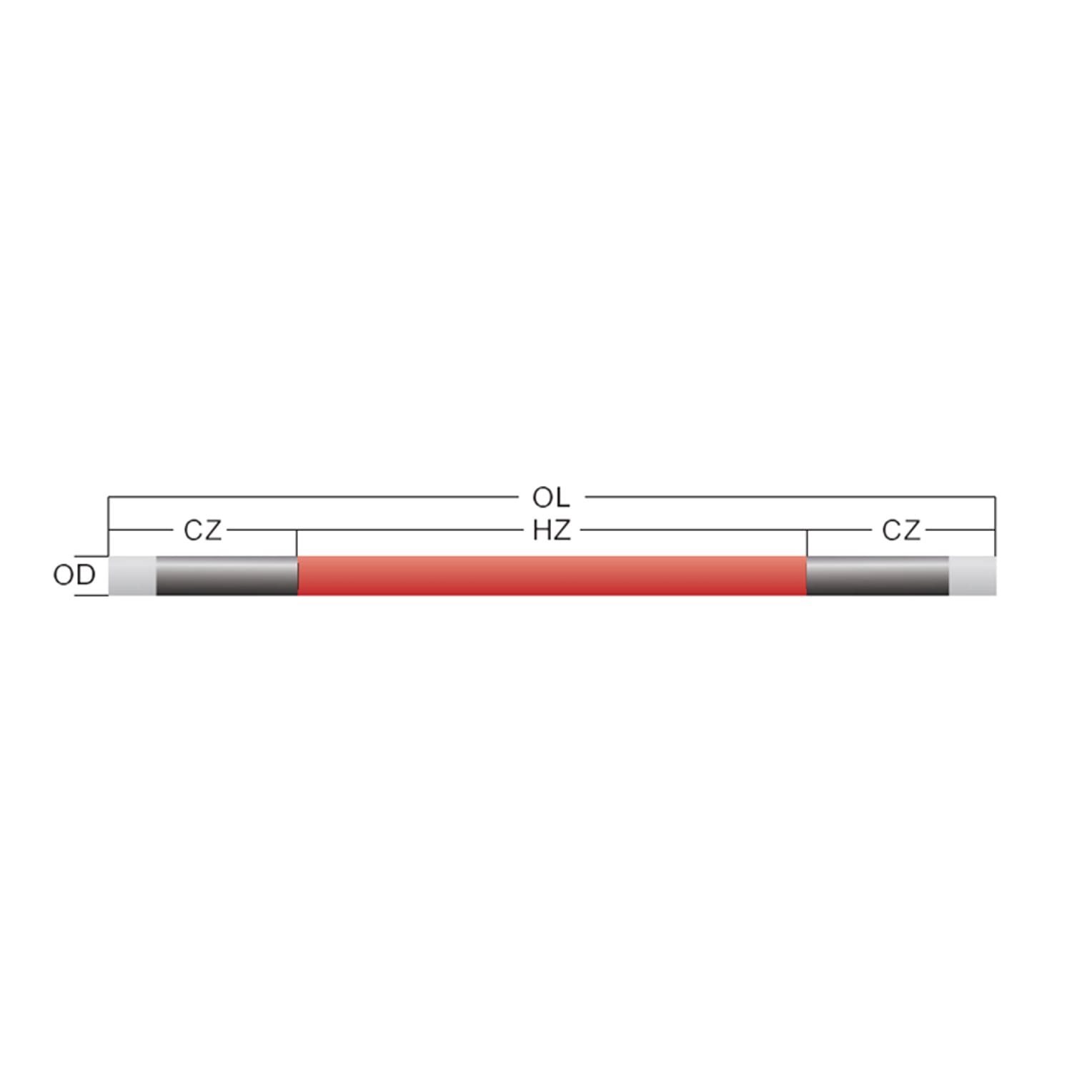
La geometría del elemento también pertenece a la lista de piezas a las que se hace referencia. A Elemento calefactor SiC tipo DH, por ejemplo, debe coincidir con la longitud de la zona caliente, los extremos fríos, el diámetro, la resistencia y la apertura del horno asumidos por el cálculo del circuito.
Cómo una conexión en serie cambia el voltaje y la resistencia
En una cadena en serie, la misma corriente fluye a través de cada elemento y se suman las resistencias individuales. Si dos elementos coincidentes tienen cada uno resistencia R, la resistencia de la cadena es aproximadamente 2R. Si se conectan tres elementos coincidentes en serie, la resistencia total es aproximadamente 3R. El diagrama de cableado del elemento calefactor de SiC debe mostrar el símbolo de cada elemento en secuencia y etiquetar el voltaje en toda la cadena.
El voltaje se divide según la resistencia. Cuando los elementos en serie están muy parecidos, su voltaje y potencia también deberían ser similares. Si un elemento tiene una resistencia sustancialmente mayor, recibe una mayor proporción del voltaje de la cadena y puede funcionar a un nivel de potencia diferente. Es por eso que un diagrama de cableado del elemento calefactor de SiC debe combinarse con un plan de adaptación de resistencia en lugar de tratar cada elemento de reemplazo como intercambiable.
Las cadenas en serie pueden reducir la corriente de zona total para una potencia determinada, pero requieren suficiente voltaje secundario para dar servicio a toda la cadena. Verifique la condición del nuevo elemento y la condición definida de mayor resistencia antes de aprobar el diagrama de cableado del elemento calefactor de SiC. Una cadena que funciona sólo en la toma más alta del transformador cuando es nueva tiene poca reserva práctica.
Cómo cambian las ramas paralelas a la corriente
Las ramas paralelas comparten el mismo voltaje de suministro y sus corrientes se suman. Si tres ramas coincidentes consumen cada una 30 A, el conductor de zona y el controlador ven aproximadamente 90 A, sujeto al diseño real del circuito. El diagrama de cableado del elemento calefactor de SiC debe mostrar cada rama por separado e indicar tanto la corriente de rama como la corriente de zona total.
La agrupación paralela se utiliza a menudo para distribuir energía a través de una cámara ancha o varias posiciones de elementos. También hace útil la comparación de ramas durante la puesta en servicio. Si una rama extrae materialmente menos corriente que sus pares, investigue la resistencia, las conexiones, la condición del conductor, la salida de control y la disposición de los elementos instalados. Un diagrama de cableado del elemento calefactor de SiC con ramas numeradas hace que esas mediciones sean rastreables.
No asuma que el mismo voltaje garantiza la misma potencia del elemento. Las ramas con diferente resistencia total consumen diferente corriente y entregan diferente potencia. Por lo tanto, el diagrama de cableado del elemento calefactor de SiC debe especificar una resistencia de rama aceptable o el método de agrupación aprobado.
Construye una zona serie-paralelo sin perder trazabilidad
Muchas zonas de hornos industriales utilizan varias cadenas en serie iguales conectadas en paralelo. Esta disposición puede adaptarse al voltaje disponible del transformador mientras distribuye la corriente a través de múltiples posiciones de elementos. En el diagrama de cableado del elemento calefactor de SiC, dibuje una cadena en serie completa por rama y luego conecte las ramas a puntos de bus secundarios comunes solo donde el diseño aprobado lo requiera.
Para cada rama, calcule la resistencia total en serie, el voltaje de la rama, la corriente de la rama y la potencia de la rama. Luego sume las corrientes y potencias de las ramas para la zona. Mantenga la tabla de cálculo junto al diagrama de cableado del elemento calefactor de SiC. Un revisor debería poder pasar de kilovatios de zona a valores de rama y finalmente al voltaje y la corriente de un elemento sin cambiar las suposiciones.
| Conexión | Lo que sigue siendo común | Qué añade | Verificarea principală a designului |
|---|---|---|---|
| Serie | Actual | Resistencia y tensiones de elementos | Coincidencia de tensión y resistencia de cadena |
| Paralelo | Voltaje | Corrientes de ramificación | Saldo total corriente y sucursal |
| Serie paralela | Voltaje a través de cadenas paralelas | Resistencia dentro de cuerdas y corriente a través de ramas | Tanto el rango de tensión como la corriente total |
Diseño para crecimiento de resistencia y agrupación de reemplazo
Los elementos calefactores de carburo de silicio aumentan la resistencia durante el servicio. Para mantener la misma potencia, el sistema de control generalmente necesita un voltaje más alto a medida que aumenta la resistencia. El diagrama de cableado del elemento calefactor de SiC debe mostrar el rango secundario utilizable del transformador o el programa de derivación e identificar los límites eléctricos del controlador, los conductores y la protección.
La práctica de reemplazo importa tanto como el diseño original. Si un elemento fallido en una cadena en serie se reemplaza por uno de resistencia sustancialmente diferente, la distribución de energía puede cambiar. Algunos sistemas requieren conjuntos coincidentes o reagrupación entre ramas. Registre el enfoque de mantenimiento permitido en el diagrama de cableado del elemento calefactor de SiC o una instrucción de servicio asociada.
Un diagrama de cableado claro del elemento calefactor de SiC debe incluir espacio para lecturas de resistencia construidas, fecha de instalación, posición del elemento y cualquier reagrupación posterior. Este historial ayuda al mantenimiento a distinguir el desarrollo normal de la resistencia de una conexión débil o un reemplazo incorrecto.
Especifique correas terminales, abrazaderas y enrutamiento de conductores
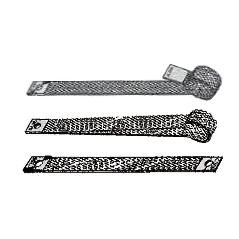
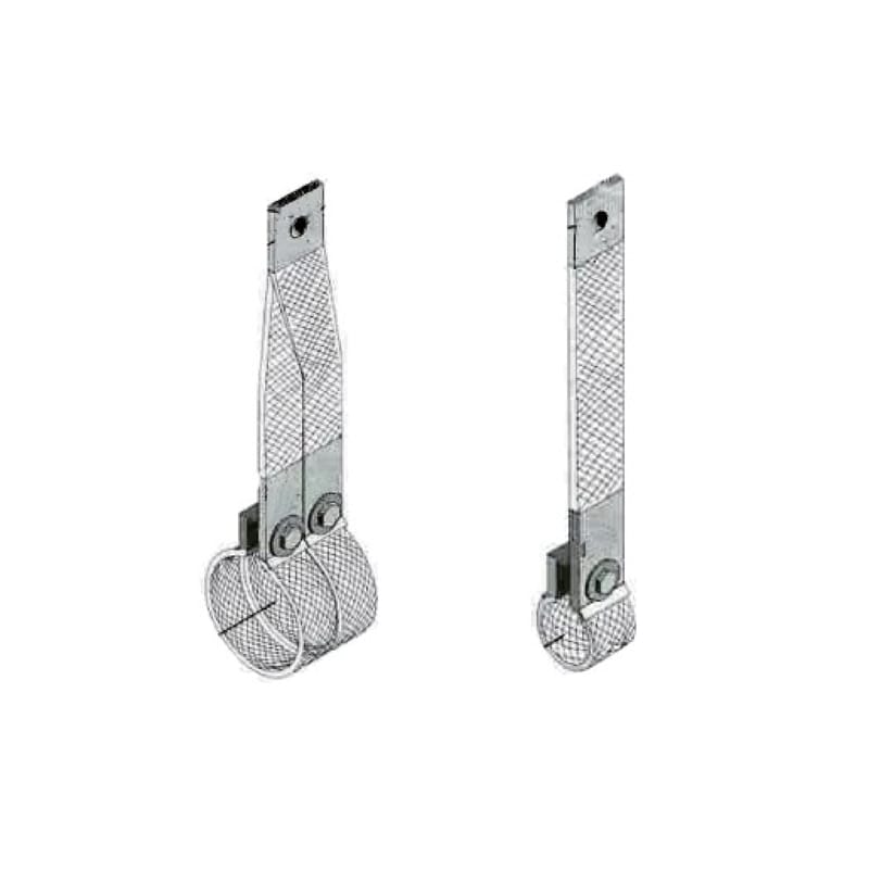
La conexión desde el conductor de suministro al extremo frío del elemento debe tolerar corriente, temperatura local, movimiento e inspección repetida. Un diagrama de cableado del elemento calefactor de SiC debe identificar el hardware del terminal en lugar de terminar en un punto genérico. El contacto flojo, las correas de tamaño insuficiente, la rigidez excesiva o el recorrido deficiente pueden crear calefacción localizada y carga mecánica.
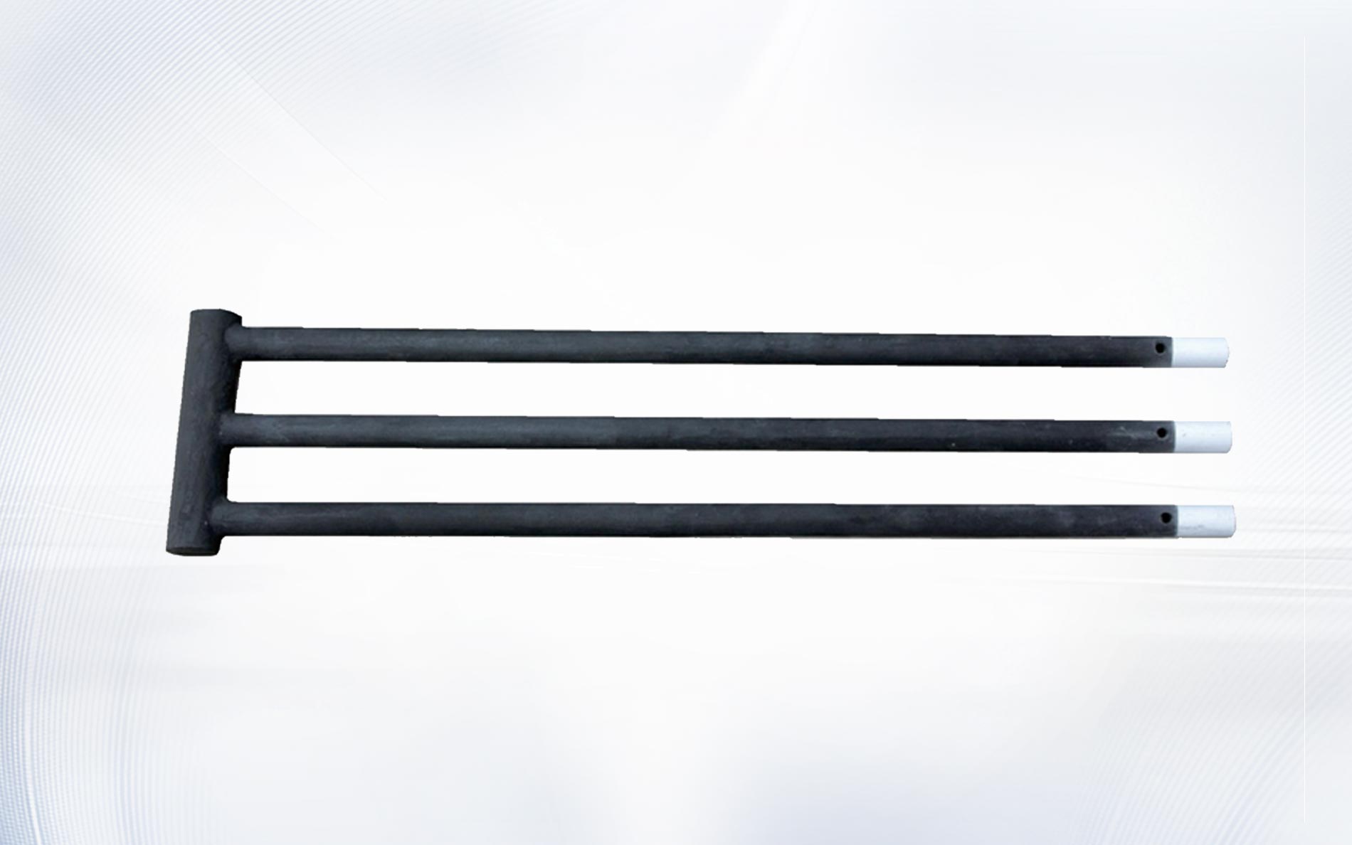
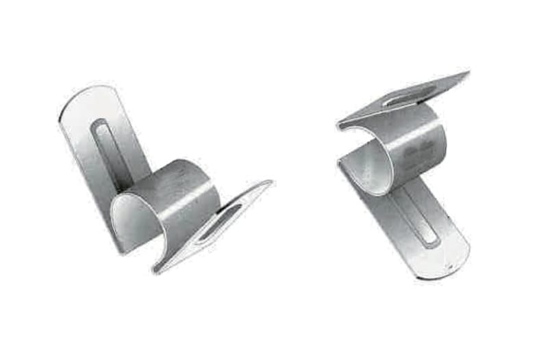
Uso aprobado tiras conductoras de aluminio, Tiras conductoras tipo G, u otros conectores especificados sólo cuando coincidan con el diseño del elemento y del horno. El abrazadera de varilla calefactora debe proporcionar el contacto requerido evitando al mismo tiempo fuerzas dañinas sobre el elemento cerámico.
Muestre el enrutamiento y el soporte para que una conexión flexible no transfiera el peso del cable, la vibración o la expansión térmica al elemento. Marque las holguras de la carcasa caliente, las aberturas refractarias y la carpintería metálica conectada a tierra. Estos detalles convierten el diagrama de cableado del elemento calefactor de SiC en un documento de instalación en lugar de un circuito puramente teórico.
Agregue información de protección, aislamiento y control
Un dibujo del circuito del calentador está incompleto sin las funciones de protección y control asociadas. El ingeniero responsable debe seleccionar medios de desconexión, protección contra sobrecorriente, controlador, transformador, conexión a tierra o unión, enclavamientos, protección contra sobretemperatura, funciones de emergencia y aislamiento seguro apropiado para el sistema. El diagrama de cableado del elemento calefactor de SiC debe hacer referencia a esos dispositivos y sus configuraciones aprobadas.
Para lugares de trabajo de EE. UU., revise los de OSHA información de normas eléctricas, requisitos de diseño relevantes como 29 CFR 1910.303, y los procedimientos de energía peligrosa del sitio a continuación 29 CFR 1910.147. Otras jurisdicciones tienen sus propios requisitos. El Descripción general de IEC 60519-1 también identifica el alcance de los requisitos generales de seguridad para instalaciones de electrocalentamiento industrial.
Las referencias de estándares no reemplazan la evaluación de riesgos del proyecto. Un diagrama de cableado del elemento calefactor de SiC debe reflejar el horno real, el sistema de suministro, el entorno, el acceso, las prácticas de mantenimiento y las reglas adoptadas localmente.
Encargue el diagrama con los valores de rama medidos
Antes de la energización, confirme la posición del elemento instalado, la resistencia, el hardware del terminal, el enrutamiento del conductor, las holguras, los dispositivos de protección, la configuración del transformador y los límites del controlador en el diagrama de cableado del elemento calefactor de SiC aprobado. Resuelva las diferencias antes del primer calentamiento en lugar de marcarlas como construidas después de la puesta en servicio.
Durante el arranque por etapas, el personal calificado debe registrar el voltaje secundario, la corriente de rama, la salida del controlador y las temperaturas relevantes utilizando procedimientos aprobados. Compare los valores de las ramas en las mismas condiciones de funcionamiento. El diagrama de cableado del elemento calefactor de SiC debe proporcionar etiquetas de elementos y puntos de prueba que coincidan con la hoja de medición.
Actualice el diagrama de cableado del elemento calefactor de SiC controlado después de los cambios aprobados. Los cambios de grifo no documentados, los elementos reagrupados o el hardware de terminal sustituido hacen que la resolución de problemas posterior sea más lenta y pueden invalidar el cálculo original.
Preguntas frecuentes
¿deben cablearse los elementos calefactores de SiC en serie o en paralelo?
Cualquiera de los dos puede ser apropiado. La elección depende de la resistencia del elemento, la potencia requerida, el voltaje disponible del transformador, la corriente del controlador, el diseño de la zona y el rango de envejecimiento planificado. El diagrama de cableado del elemento calefactor de SiC debe documentar por qué el grupo seleccionado se ajusta a todos esos límites.
¿por qué los elementos de la serie deben coincidir con la resistencia?
Los elementos de la serie transportan la misma corriente, pero un elemento de mayor resistencia desarrolla una mayor caída de voltaje y diferente potencia. La coincidencia reduce el desequilibrio y hace que los cálculos del diagrama de cableado del elemento calefactor de SiC sean más representativos del funcionamiento real.
¿Se pueden conectar elementos directamente a la red eléctrica?
No lo asumas. Muchos sistemas de hornos utilizan un transformador y un rango secundario controlado para igualar la resistencia del elemento y adaptarse al envejecimiento. Los ingenieros calificados deben diseñar el circuito completo y aprobar el diagrama de cableado del elemento calefactor de SiC.
¿Qué valores se deben escribir al lado de cada rama?
Registre la cantidad de elementos, la disposición en serie/paralelo, la base de resistencia, la resistencia de rama, el voltaje, la corriente, la potencia, la referencia del conductor y del terminal, la protección y los números de posición del elemento que se muestran en el diagrama de cableado del elemento calefactor de SiC.
¿Qué debería incluirse en una consulta con un proveedor?
Envíe el diagrama de cableado actual del elemento calefactor de SiC, el dibujo del elemento, los datos de resistencia, el rango secundario del transformador, la corriente de rama medida, la temperatura del horno, la atmósfera, el ciclo, la cantidad, las fotografías de los terminales y la fecha de reemplazo requerida.
Utilice el diagrama de cableado como registro de ingeniería compartido
El dibujo más útil conecta los cálculos eléctricos con las posiciones de los elementos físicos, el hardware de los terminales, el rango de control, las funciones de seguridad y las mediciones de puesta en servicio. Un diagrama de cableado del elemento calefactor de SiC en buen estado ayuda a los diseñadores a revisar el circuito original, especificar reemplazos compatibles y diagnosticar el comportamiento desigual de las ramas.
Para un proyecto de horno de reemplazo o nuevo, póngase en contacto con el material Qixiang con el dibujo de elementos, información del circuito, alcance del transformador, atmósfera y condiciones de operación. El equipo puede discutir los elementos y accesorios de conexión adecuados mientras sus ingenieros eléctricos calificados aprueban el diseño completo del circuito y la seguridad.