A furnace wiring concept can look simple on paper—connect several resistive elements to a transformer and control the output—but one incorrect assumption about resistance, voltage, or grouping can produce unequal power, excessive current, or no useful voltage reserve as the elements age. A good SiC heating element wiring diagram therefore has to show more than lines between terminals.
This guide explains how to read and prepare a SiC heating element wiring diagram for series, parallel, and series-parallel furnace zones. It is intended for equipment designers, maintenance engineers, and technical buyers who need to communicate circuit requirements clearly. Final design, protection, installation, and energized work must be completed by qualified personnel under the standards and regulations applicable to the site.
Define the electrical boundary shown on the diagram
Start by naming the boundary of the SiC heating element wiring diagram. A complete furnace may contain several independently controlled zones, and each zone may contain several branches. The drawing should distinguish incoming supply, primary protection, transformer, power controller, zone switching, branch protection where used, elements, terminals, and grounding or bonding provisions.
- Identify the furnace and zone number.
- State the supply system, frequency, and transformer primary connection.
- Show the secondary voltage range or taps available to the zone.
- Number every branch and every element position.
- Record the resistance reference condition used for calculations.
- Mark the approved conductor, terminal, protection, and isolation details.
The NIST overview of electrical SI units provides the unit relationships for amperes, volts, watts, and ohms. Use those symbols consistently on the SiC heating element wiring diagram so a reviewer can trace every power and current calculation.
Understand one element before grouping several
For one resistive element, the core relationships are P = V × I, V = I × R, P = I²R, and P = V²/R. Each value must describe the same electrical boundary. If resistance is for one element, voltage and current must also be for that element. Mixing branch resistance with per-element voltage is a frequent source of errors in a SiC heating element wiring diagram.
Use the resistance specified for the relevant condition. Silicon carbide element resistance changes with temperature and service history, so the drawing or calculation note should not simply say “R” without identifying the basis. A useful SiC heating element wiring diagram includes both the design resistance and the resistance grouping or tolerance required for installation.
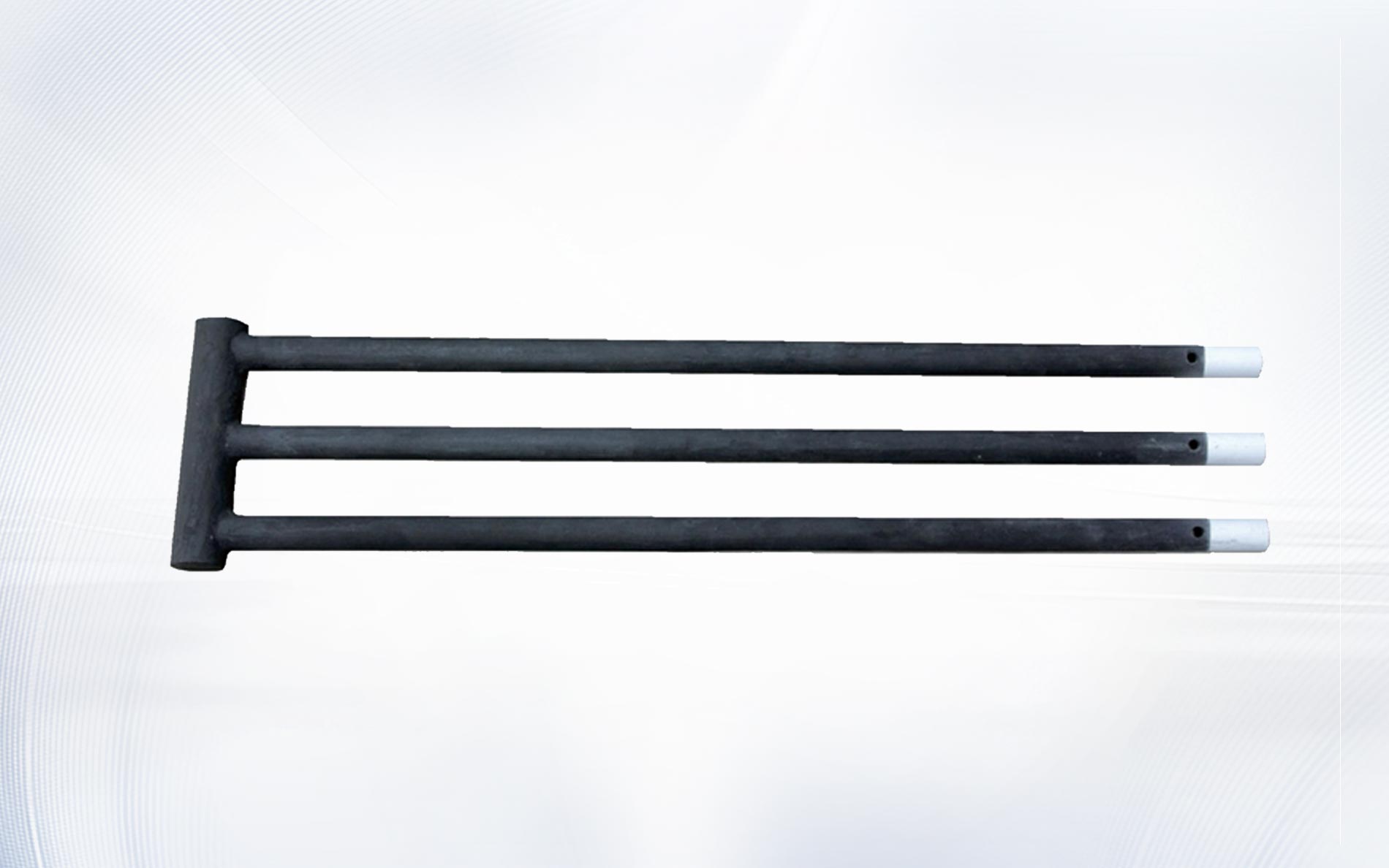
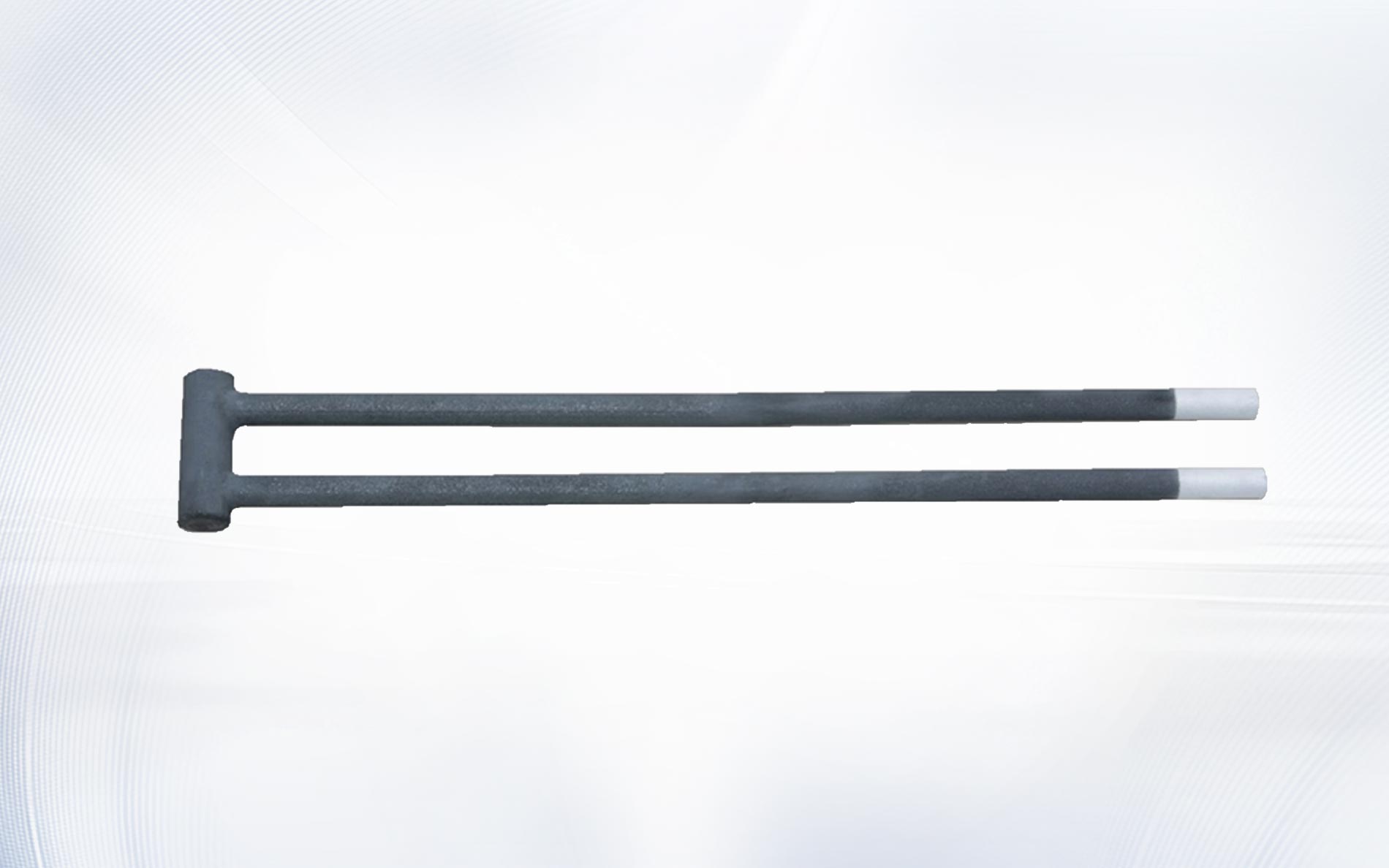
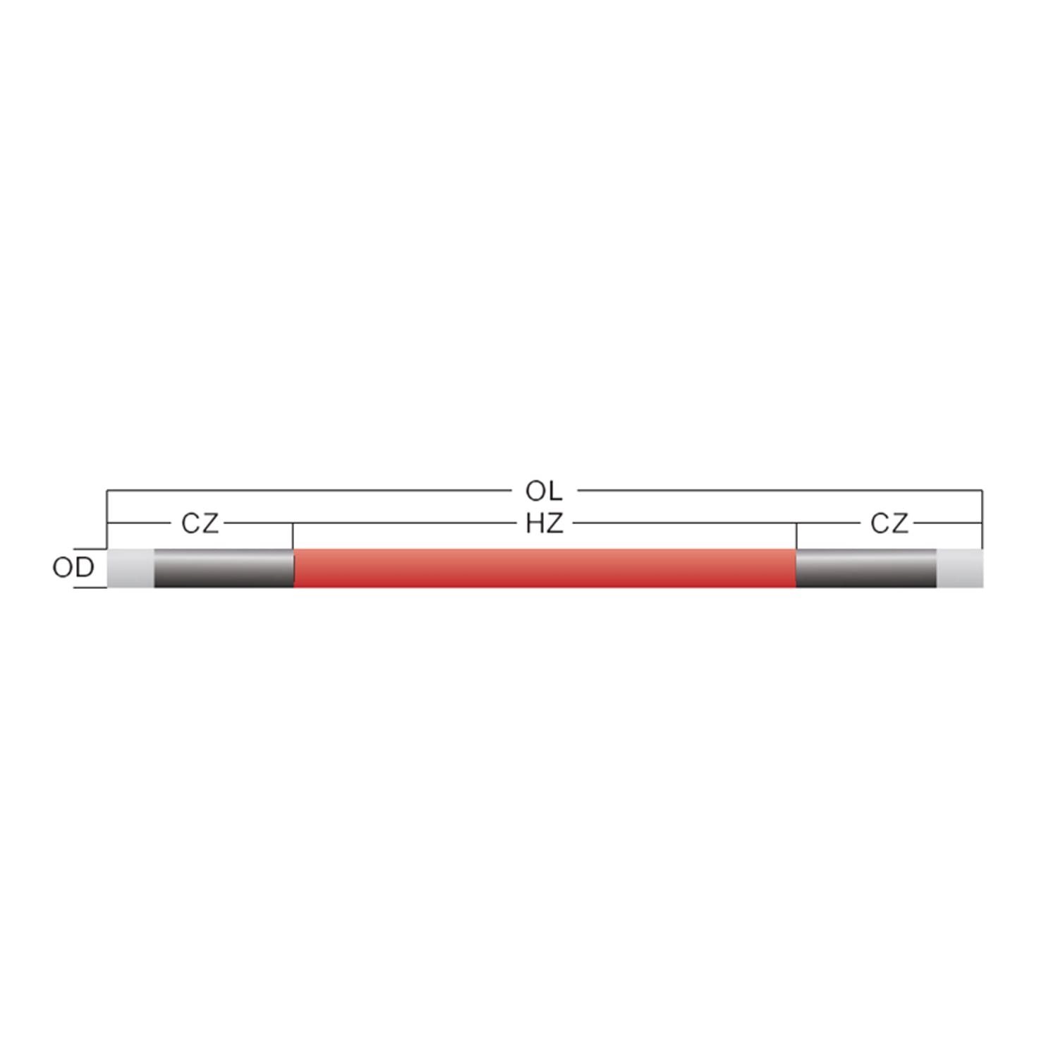
Element geometry also belongs on the referenced parts list. A DH type SiC heating element, for example, must match the hot-zone length, cold ends, diameter, resistance, and furnace opening assumed by the circuit calculation.
How a series connection changes voltage and resistance
In a series string, the same current flows through every element and the individual resistances add. If two matched elements each have resistance R, the string resistance is approximately 2R. If three matched elements are connected in series, total resistance is approximately 3R. The SiC heating element wiring diagram should show each element symbol in sequence and label the voltage across the complete string.
Voltage divides according to resistance. When series elements are closely matched, their voltage and power should also be similar. If one element has substantially higher resistance, it receives a larger share of the string voltage and can operate at a different power level. That is why a SiC heating element wiring diagram must be paired with a resistance-matching plan rather than treating every replacement element as interchangeable.
Series strings can reduce total zone current for a given power, but they require enough secondary voltage to serve the entire string. Check the new-element condition and the defined higher-resistance condition before approving the SiC heating element wiring diagram. A string that works only at the transformer’s highest tap when new has little practical reserve.
How parallel branches change current
Parallel branches share the same supply voltage and their currents add. If three matched branches each draw 30 A, the zone conductor and controller see approximately 90 A, subject to the actual circuit design. The SiC heating element wiring diagram should display each branch separately and state both branch current and total zone current.
Parallel grouping is often used to distribute power across a wide chamber or several element positions. It also makes branch comparison useful during commissioning. If one branch draws materially less current than its peers, investigate resistance, connections, conductor condition, control output, and the installed element arrangement. A SiC heating element wiring diagram with numbered branches makes those measurements traceable.
Do not assume equal voltage guarantees equal element power. Branches with different total resistance draw different current and deliver different power. The SiC heating element wiring diagram should therefore specify acceptable branch resistance or the approved grouping method.
Build a series-parallel zone without losing traceability
Many industrial furnace zones use several equal series strings connected in parallel. This arrangement can fit the available transformer voltage while distributing current across multiple element positions. On the SiC heating element wiring diagram, draw one complete series string per branch, then connect the branches to common secondary bus points only where the approved design requires.
For each branch, calculate total series resistance, branch voltage, branch current, and branch power. Then sum branch currents and powers for the zone. Keep the calculation table beside the SiC heating element wiring diagram. A reviewer should be able to move from zone kilowatts to branch values and finally to the voltage and current of one element without changing assumptions.
| Connection | What remains common | What adds | Main design check |
|---|---|---|---|
| Series | Current | Resistance and element voltages | String voltage and resistance matching |
| Parallel | Voltage | Branch currents | Total current and branch balance |
| Series-parallel | Voltage across parallel strings | Resistance within strings and current across branches | Both voltage range and total current |
Design for resistance growth and replacement grouping
Silicon carbide heating elements increase resistance during service. To maintain the same power, the control system generally needs a higher voltage as resistance rises. The SiC heating element wiring diagram should show the usable transformer secondary range or tap schedule and identify the electrical limits of the controller, conductors, and protection.
Replacement practice matters as much as original design. If a failed element in a series string is replaced with one of substantially different resistance, power distribution can shift. Some systems require matched sets or regrouping across branches. Record the permitted maintenance approach on the SiC heating element wiring diagram or an associated service instruction.
A clear SiC heating element wiring diagram should include space for as-built resistance readings, installation date, element position, and any later regrouping. This history helps maintenance distinguish normal resistance development from a weak connection or incorrect replacement.
Specify terminal straps, clamps, and conductor routing
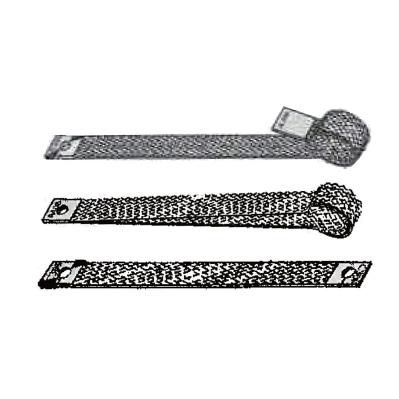
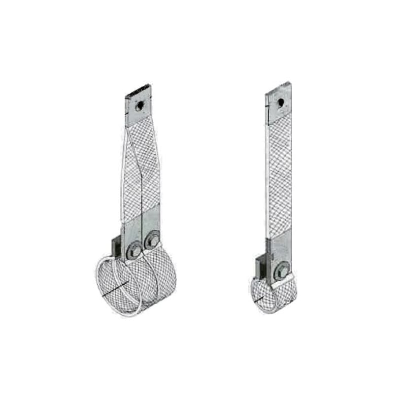
The connection from the supply conductor to the element cold end must tolerate current, local temperature, movement, and repeated inspection. A SiC heating element wiring diagram should identify terminal hardware rather than ending at a generic dot. Loose contact, undersized straps, excessive stiffness, or poor routing can create localized heating and mechanical load.
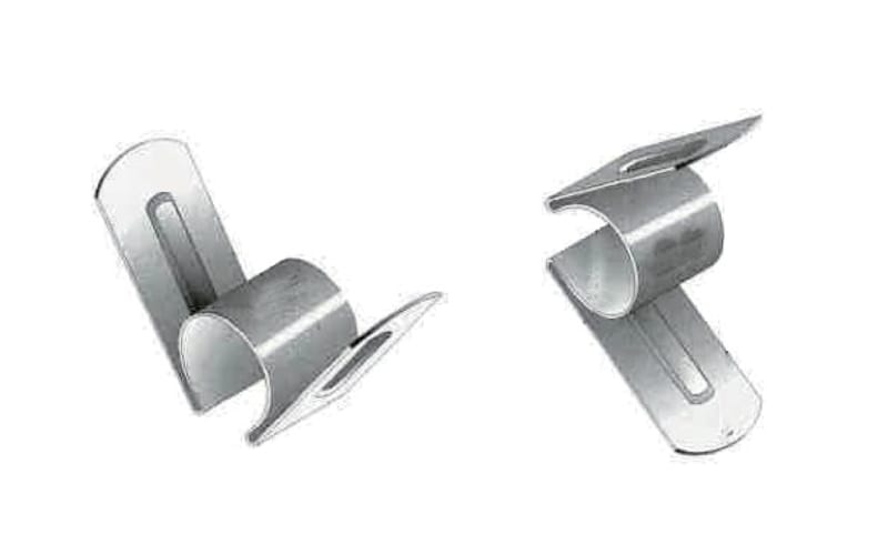
Use approved aluminum conductive strips, G type conductive strips, or other specified connectors only when they match the element and furnace design. The heating rod clamp must provide the required contact while avoiding damaging force on the ceramic element.
Show routing and support so a flexible connection does not transfer cable weight, vibration, or thermal expansion into the element. Mark clearances from hot casing, refractory openings, and grounded metalwork. These details turn the SiC heating element wiring diagram into an installation document rather than a purely theoretical circuit.
Add protection, isolation, and control information
A heater circuit drawing is incomplete without the associated protective and control functions. The responsible engineer must select disconnecting means, overcurrent protection, controller, transformer, grounding or bonding, interlocks, overtemperature protection, emergency functions, and safe isolation appropriate to the system. The SiC heating element wiring diagram should reference those devices and their approved settings.
For U.S. workplaces, review OSHA’s electrical standards information, relevant design requirements such as 29 CFR 1910.303, and the site’s hazardous-energy procedures under 29 CFR 1910.147. Other jurisdictions have their own requirements. The IEC 60519-1 overview also identifies the scope of general safety requirements for industrial electroheating installations.
Standards references do not replace the project risk assessment. A SiC heating element wiring diagram must reflect the actual furnace, supply system, environment, access, maintenance practice, and locally adopted rules.
Commission the diagram with measured branch values
Before energization, confirm installed element position, resistance, terminal hardware, conductor routing, clearances, protective devices, transformer configuration, and controller limits against the approved SiC heating element wiring diagram. Resolve differences before first heat rather than marking them as as-built after commissioning.
During staged startup, qualified personnel should record secondary voltage, branch current, controller output, and relevant temperatures using approved procedures. Compare branch values at the same operating condition. The SiC heating element wiring diagram should provide element and test-point labels that match the measurement sheet.
Update the controlled SiC heating element wiring diagram after approved changes. Undocumented tap changes, regrouped elements, or substituted terminal hardware make later troubleshooting slower and can invalidate the original calculation.
Frequently asked questions
Should SiC heating elements be wired in series or parallel?
Either may be appropriate. The choice depends on element resistance, required power, available transformer voltage, controller current, zone layout, and the planned aging range. The SiC heating element wiring diagram should document why the selected grouping fits all of those limits.
Why must series elements be resistance matched?
Series elements carry the same current, but a higher-resistance element develops a larger voltage drop and different power. Matching reduces imbalance and makes the SiC heating element wiring diagram calculations more representative of actual operation.
Can elements be connected directly to the mains supply?
Do not assume so. Many furnace systems use a transformer and controlled secondary range to match element resistance and accommodate aging. Qualified engineers must design the complete circuit and approve the SiC heating element wiring diagram.
What values should be written beside each branch?
Record element quantity, series/parallel arrangement, resistance basis, branch resistance, voltage, current, power, conductor and terminal reference, protection, and the element position numbers shown on the SiC heating element wiring diagram.
What should be included in a supplier inquiry?
Send the current SiC heating element wiring diagram, element drawing, resistance data, transformer secondary range, measured branch current, furnace temperature, atmosphere, cycle, quantity, terminal photographs, and the required replacement date.
Use the wiring diagram as a shared engineering record
The most useful drawing connects electrical calculations to physical element positions, terminal hardware, control range, safety functions, and commissioning measurements. A well-maintained SiC heating element wiring diagram helps designers review the original circuit, procurement specify compatible replacements, and maintenance diagnose unequal branch behavior.
For a replacement or new furnace project, contact Qixiang Material with the element drawing, circuit information, transformer range, atmosphere, and operating conditions. The team can discuss suitable elements and connection accessories while your qualified electrical engineers approve the full circuit and safety design.