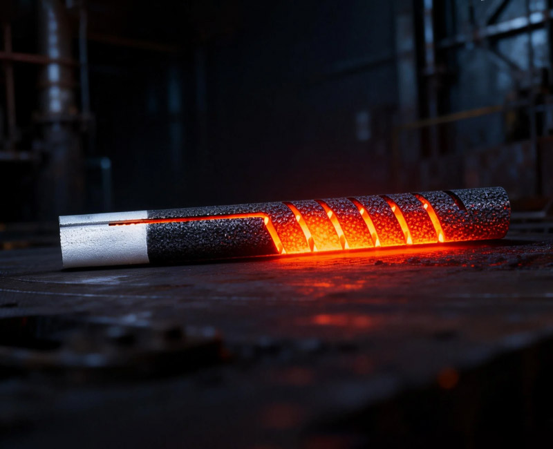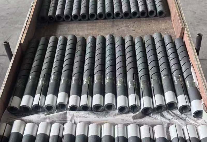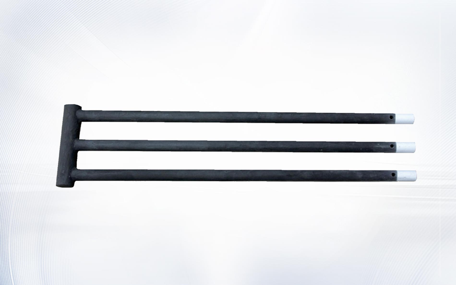
There is no single service-hour number that predicts every furnace. Element geometry, surface loading, temperature, atmosphere, cycling, installation, connections, resistance grouping, and voltage reserve all affect usable life. Extending silicon carbide heating element life therefore starts by defining the operating conditions and maintenance evidence that the plant can actually control.
This guide gives furnace owners a practical program for extending silicon carbide heating element life without making unsupported lifetime promises. It focuses on preventing avoidable stress, tracking resistance and electrical performance, and recognizing when furnace or process conditions—not the element alone—are accelerating change.
Define what “end of life” means for the furnace
An element may still conduct electricity but no longer deliver required zone power within the available voltage range. Another may be electrically usable but mechanically damaged or unsuitable after a process change. A silicon carbide heating element life program should define replacement criteria for resistance, control authority, branch balance, physical condition, process performance, and safe installation.
- Can the branch deliver required power without exceeding approved voltage and current limits?
- Does useful controller authority remain at normal and recovery duty?
- Are element surfaces, transitions, cold ends, and terminals in acceptable condition?
- Does the zone meet loaded temperature and recovery requirements?
- Can replacements be grouped with the remaining elements under the approved strategy?
Document these criteria before an outage. A clear endpoint makes silicon carbide heating element life decisions less dependent on one alarm or a visual impression.
Create a baseline at installation
Record element manufacturer, type, drawing revision, hot-zone and cold-end dimensions, position, resistance and reference condition, grouping, installation date, transformer tap, voltage, branch current, controller output, furnace temperature, atmosphere, and load. This baseline is the starting point for measuring silicon carbide heating element life.
Photograph the installed element, supports, penetrations, straps, clamps, and conductor routing before covers are closed. Use the SiC startup procedure to establish comparable electrical and temperature readings during staged commissioning.
Without baseline resistance and circuit data, later maintenance may confuse a different tap, changed load, poor connection, or measurement method with normal silicon carbide heating element life development.
Keep surface loading within the approved envelope
High watts per unit of hot-zone surface generally increase element temperature relative to the chamber. The suitable limit depends on element design, furnace temperature, atmosphere, load radiation, spacing, and service pattern. To support silicon carbide heating element life, calculate surface loading for every normal and recovery condition rather than using total furnace kilowatts alone.
Use measured voltage and current to confirm delivered power. If an element is shortened, regrouped, or replaced with a different diameter, recalculate its surface area and electrical operating point. The SiC power calculation guide provides the element-level workflow.
Adding voltage to recover a slow furnace can reduce silicon carbide heating element life when the true problem is insulation damage, door leakage, a heavier load, blocked radiation, or sensor error. Diagnose the heat balance before raising element power.
Control atmosphere, moisture, and process deposits
Gas composition, moisture, pressure, purge, exhaust, load emissions, seals, and process deposits affect element surface behaviour. Record actual conditions through the cycle, not only the nominal atmosphere name. Stable atmosphere control is a major contributor to predictable silicon carbide heating element life.
Inspect door seals, penetrations, gas inlets, exhaust paths, pressure control, and analyser status. Track changes after new products, binders, cleaning agents, refractory work, or atmosphere recipes. The SiC oxidation guide explains how to compare atmosphere, moisture, deposits, temperature, and resistance evidence.
The U.S. Department of Energy’s process heating resources emphasize a systems approach. For silicon carbide heating element life, the load, enclosure, atmosphere, controls, and heat source should be investigated together.
Use controlled starts, restarts, and cooldowns
Cold refractory, hot restart, door opening, cold loads, rapid gas-flow changes, and uncontrolled recovery can create large temperature gradients. Approved output limits and ramps help protect silicon carbide heating element life by controlling the transition between operating states.
Separate cold-start, hot-restart, normal production, trip recovery, and cooldown logic. Trend controller output with chamber temperature and door or conveyor state. The thermal shock prevention guide provides the evidence and commissioning checks that should support these recipes and protect silicon carbide heating element life.
Control recipe changes. A small increase in ramp or recovery output can become a permanent silicon carbide heating element life risk if it is not reviewed against refractory, load, atmosphere, and electrical limits.
Match resistance when installing replacements
In a series string, current is common while voltage and power divide according to resistance. In parallel branches, unequal resistance produces unequal current and power. Poor matching can make one part of the furnace work harder and reduce silicon carbide heating element life even when total zone output appears normal.
Measure using the approved method and reference condition, then group elements according to the supplier and furnace design. Record every replacement and regrouping on the as-built schedule. Do not mix new and aged elements merely because their dimensions match.
| Maintenance indicator | Useful comparison | Possible action |
|---|---|---|
| Rising controller output | Same load, temperature, tap, and atmosphere | Check resistance, losses, sensor, and connections |
| One low-current branch | Voltage and resistance of peer branches | Inspect grouping, element continuity, and terminals |
| Local terminal heating | Comparable straps, clamps, and current | Correct contact and conductor support under approved procedure |
| Repeated break at one position | Opening, support, gas flow, load radiation | Correct the local installation or process condition |
| Reduced recovery across all zones | Load, insulation, doors, element power, sensors | Restore furnace performance before adding power |
Maintain terminals and flexible connections
Loose or unsuitable connections create local resistance and heat at the cold end. Inspect straps, clamps, conductor flexibility, routing, discoloration, contamination, and support during planned shutdowns. Good terminal condition protects both reliable power delivery and silicon carbide heating element life.
Use compatible aluminum conductive strips and heating rod clamps only as approved for the element and furnace. Do not let cable weight, vibration, or rigid bus movement load the ceramic terminal section.
For U.S. servicing work, follow OSHA’s control of hazardous energy standard together with site procedures. Safe isolation is essential before connection work intended to improve silicon carbide heating element life.
The IEC 60519-1 overview identifies the scope of general safety requirements for industrial electroheating installations. Applicable standards and project engineering govern maintenance performed to support silicon carbide heating element life.
Preserve voltage reserve as resistance increases
Delivering the same power at higher resistance requires more voltage. A suitable transformer and controller plan gives new elements stable low-range control and aged elements later-life reserve. Operating new elements near the maximum available voltage leaves little room to preserve silicon carbide heating element life and production capability.
Set measurable tap-change criteria based on comparable resistance, voltage, current, controller output, load, and recovery data. The voltage control guide explains how to build this operating envelope.
Do not use an undocumented tap increase as a substitute for diagnosis. If one branch behaves differently, inspect it before raising voltage for the whole zone. Protecting healthy branches is part of managing silicon carbide heating element life.
Keep elements clean, aligned, and free to expand
Inspect refractory openings, supports, seals, kiln furniture, deposits, and clearances. A tight opening, misalignment, repaired refractory, conductor load, or product contact can create mechanical stress. Correct these conditions under the approved furnace design to support silicon carbide heating element life.
Use only an approved cleaning method. Photograph deposits before removal and record their location relative to gas inlets and loads. Cleaning can restore inspection access, but it does not solve the source of contamination.
Trend a small set of comparable life indicators
Collect branch resistance, secondary voltage, current, controller output, tap, loaded recovery time, atmosphere, and inspection findings at defined conditions. More data is not automatically better; consistent context is what makes silicon carbide heating element life trends actionable.
Compare equivalent loads and recipe stages. Separate planned tap changes from unexplained changes. NIST Technical Note 1297 explains general principles for expressing measurement uncertainty; use an appropriate method before reacting to a small resistance difference.
Review trends on a defined schedule and after every significant process, atmosphere, refractory, controller, or wiring change. The objective is to act before control reserve, branch balance, or physical condition reaches the approved silicon carbide heating element life limit.
Frequently asked questions
How long should a silicon carbide element last?
There is no responsible universal hour value. Silicon carbide heating element life depends on electrical loading, temperature, atmosphere, cycles, installation, connections, furnace condition, and the plant’s replacement criteria.
Does lower power always increase life?
Lower surface loading may reduce element temperature, but the furnace still needs to meet its process duty. Select power from a complete heat balance and approved operating envelope.
Should old and new elements be mixed?
Only under an approved resistance-matching and circuit strategy. Equal dimensions do not guarantee compatible voltage and power distribution.
Which maintenance record matters most?
A comparable set of resistance, voltage, current, controller output, tap, load, atmosphere, temperature, and inspection data is more useful than one isolated reading for managing silicon carbide heating element life.
What should be sent for a life-improvement review?
Send element drawings, resistance history, circuit and taps, voltage and current trends, surface loading, temperature, atmosphere, cycles, load, installation and terminal photos, failure positions, service history, and quantity.
Manage life as an operating system
Reliable service comes from correct specification, verified installation, controlled power and atmosphere, compatible resistance groups, maintained terminals, usable voltage reserve, and comparable trend data. Managing those variables gives a plant practical control over silicon carbide heating element life without relying on unsupported promises.
For a new design or replacement program, contact Qixiang Material with the element drawing, circuit, resistance history, power, temperature, atmosphere, cycle, load, installation details, and quantity. The team can discuss suitable SiC elements and accessories while the responsible engineers approve the complete furnace and maintenance plan.