First heat is the point when drawings, purchased parts, refractory work, electrical installation, controls, atmosphere systems, and operating procedures meet the real furnace. Treating it as a normal production cycle can hide wiring errors, unsuitable resistance groups, constrained elements, wet refractory, or incorrect controller limits. A SiC heating element startup procedure should release each system in stages and preserve baseline data.
This guide provides a practical SiC heating element startup procedure for a new furnace, a rebuilt hot zone, or a major element replacement. It does not replace the equipment manufacturer’s commissioning instructions, site risk assessment, or work by qualified electrical, controls, mechanical, refractory, and process personnel.
Define the startup boundary and authorization
Before field checks begin, state exactly what the startup covers: complete furnace, one rebuilt zone, new transformer, controller replacement, atmosphere modification, or element change. The SiC heating element startup procedure should name the commissioning leader, discipline owners, stop-work authority, required permits, and the person who can approve each hold point.
- Approved mechanical, electrical, control, and process drawings
- Element data, resistance records, and installation positions
- Protection, interlock, alarm, and emergency-function test plan
- Refractory dry-out and atmosphere-system requirements
- Permitted test load and production acceptance criteria
- Measurement instruments, calibration status, and safe test methods
Record open items and decide which prevent energization. A SiC heating element startup procedure is a release document, not a place to hide unfinished work under “monitor during operation.”
Stage 1: Complete a de-energized mechanical inspection
Verify each element against the drawing and position schedule. Check type, overall length, hot-zone length, cold ends, diameter, resistance identification, orientation, and quantity. The SiC heating element startup procedure should require photographs or sign-off before covers make the installation difficult to see.
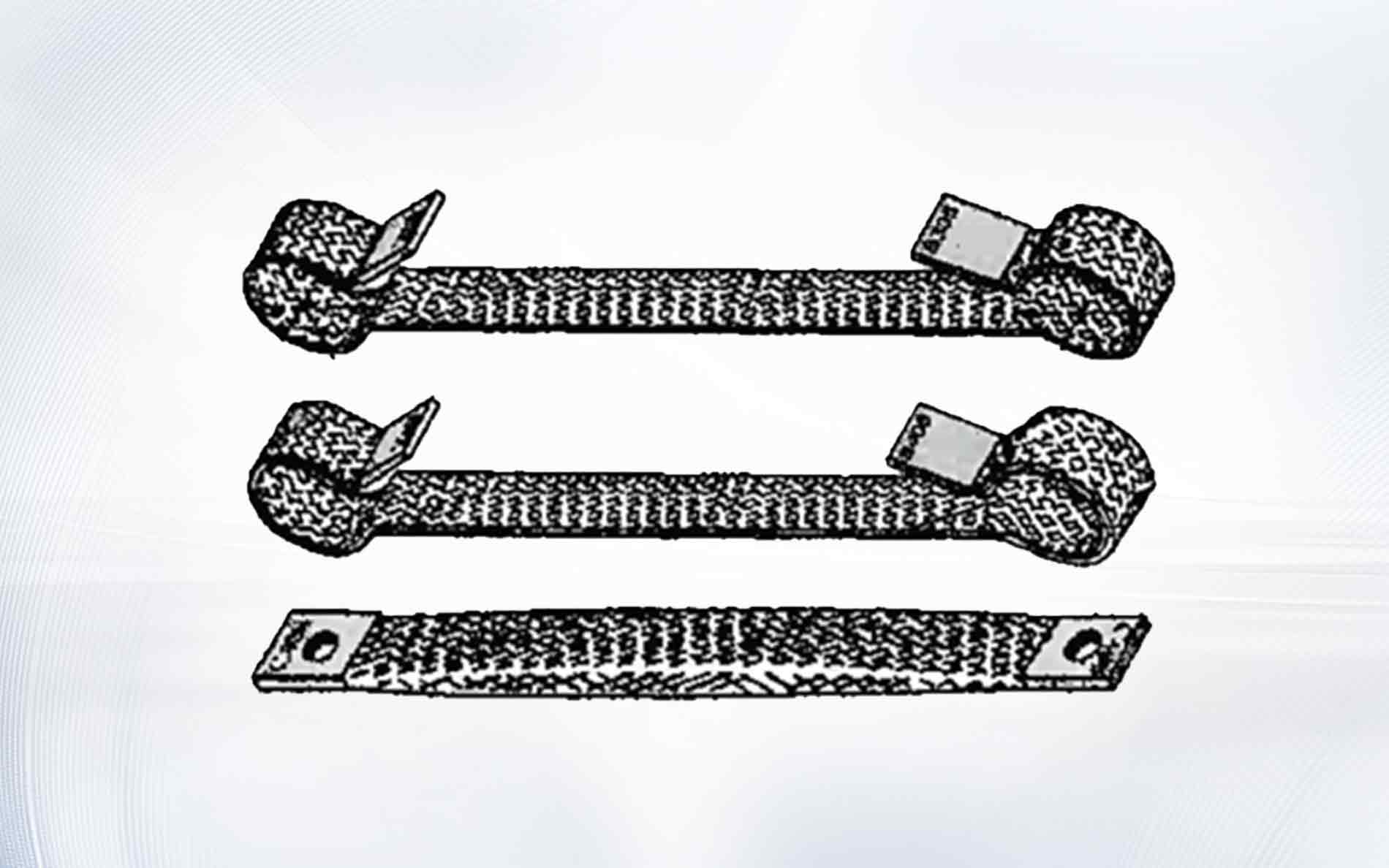
Inspect refractory openings, alignment, supports, seals, clearances, and distance to kiln furniture or metalwork. Confirm that conductor weight and rigid buswork do not load the element. Multi-leg elements must not be twisted or forced to fit. Correct mechanical problems before the SiC heating element startup procedure continues.
Review the SiC cold-end sizing guide when verifying wall penetration and terminal access. Mechanical acceptance belongs near the beginning of the SiC heating element startup procedure because later energization cannot correct a constrained installation.

Stage 2: Verify resistance groups and as-built wiring
Record the approved resistance value for every element or branch using the specified method and reference condition. Compare the grouping with the design schedule. A SiC heating element startup procedure should stop if an element is in the wrong position, a series string contains an unacceptable mismatch, or the measured circuit does not match the drawing.
Trace every branch from transformer secondary to element and return. Confirm phase assignment, series and parallel links, conductor sizes, terminal hardware, clearances, identification, grounding or bonding, and protection. The SiC wiring diagram guide explains how to make element and branch boundaries visible.
Use the NIST overview of electrical SI units to keep volts, amperes, watts, and ohms consistent. The calculated and measured values in the SiC heating element startup procedure must refer to the same element, branch, or complete zone.
Stage 3: Test controls, protection, and interlocks
Complete approved cold checks for disconnecting means, overcurrent protection, transformer configuration, controller settings, sensors, alarms, overtemperature protection, door or access interlocks, cooling, purge, exhaust, emergency functions, and safe shutdown. Document test result, expected response, observed response, and reviewer in the SiC heating element startup procedure.
Do not bypass an interlock to keep the schedule. Resolve failed tests and repeat them after changes. Retain the result in the SiC heating element startup procedure. For U.S. servicing and commissioning work, OSHA’s control of hazardous energy standard is relevant alongside site procedures and other applicable requirements.
Confirm transformer taps and controller limits against new-element resistance and the planned later-life range. The SiC voltage control guide explains why the SiC heating element startup procedure should not begin normal operation with the controller already near its upper or lower practical limit.
Stage 4: Release refractory, atmosphere, and load conditions
New or repaired refractory may require a controlled dry-out before normal heat-up. Confirm curing time, initial moisture condition, exhaust path, atmosphere restrictions, and the approved dry-out schedule. Water release changes heat demand and local gas conditions, so the SiC heating element startup procedure must coordinate refractory and element requirements.
Verify atmosphere gas, purity, flow, pressure, purge sequence, exhaust, seals, analyser status, and interlocks. Define whether first heat is empty, uses a test load, or uses approved production material. The U.S. Department of Energy’s process heating resources reinforce the need to evaluate heat source, enclosure, controls, and load as a system.
Do not introduce an unapproved wet, cold, chemically different, or oversized load during commissioning. The SiC heating element startup procedure needs a known thermal and atmosphere condition so unexpected behaviour can be traced.
Stage 5: Apply power in controlled increments
Begin only after all energization hold points are signed. Use the approved tap, output limit, ramp, and atmosphere state. At each stage, allow readings to stabilize as required and compare voltage, branch current, controller output, temperature, alarms, and visible conditions with the SiC heating element startup procedure limits.
| Hold point | Confirm before release | Record |
|---|---|---|
| Before energization | Mechanical, circuit, protection, sensor, atmosphere, and permit status | Sign-offs and open-item disposition |
| Initial low output | Correct branch current direction and no abnormal connection heating | Voltage, current, output, visual inspection |
| Intermediate output | Branch balance, expected power, stable controls | All zone electrical and temperature values |
| First temperature hold | Refractory and atmosphere response within plan | Trend, moisture or exhaust observations, alarms |
| Normal operating range | Useful controller authority and acceptable loaded performance | Baseline data and acceptance results |
If measured values conflict with calculations, pause and resolve the boundary, instrument, wiring, resistance, tap, or controller state. The SiC current calculation guide helps compare element, branch, and total secondary amperes during the SiC heating element startup procedure.
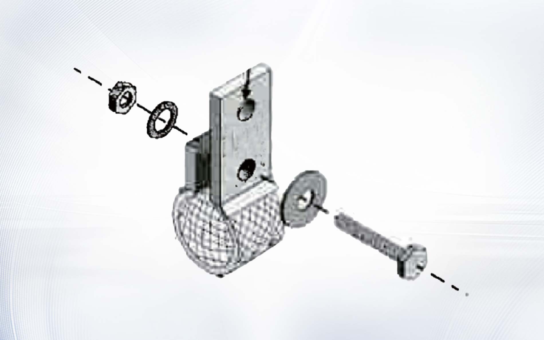
Inspect connections using approved methods. Localized heat, arcing, smell, noise, unstable current, or visible movement requires a controlled stop. Do not tighten or reposition energized hardware.
Stage 6: Establish branch and zone baselines
At defined operating points, record transformer tap, controller mode and output, secondary voltage, every accessible branch current, element or branch resistance basis, chamber temperatures, atmosphere, load, and time. These values become the baseline against which later resistance growth and connection problems are judged.
Compare branches only under the same control state. A value taken while the controller is modulating cannot be compared with a steady full-output calculation without context. The SiC heating element startup procedure should specify measurement timing and instrument method.
NIST describes thermocouple calibration services and uncertainties. Record calibration and location for the sensors used to accept temperature performance in the SiC heating element startup procedure.
Stage 7: Verify trip, restart, and controlled shutdown behaviour
Test only scenarios authorized by the commissioning plan. Confirm that power is removed or limited as designed, alarms identify the condition, state is retained appropriately, and restart requires the approved checks. A SiC heating element startup procedure should distinguish cold restart from hot restart rather than returning immediately to the previous command.
The thermal shock prevention guide explains why element temperature gradients and power steps matter during recovery. Verify that a brief sensor or supply interruption cannot cause uncontrolled maximum output.
Confirm planned cooldown rules for power, gas flow, exhaust, fans, doors, and loading. Rapid cooling can be as significant as rapid heating. Record the accepted sequence as part of the SiC heating element startup procedure.
Stage 8: Prove performance with a representative load
An empty furnace can verify basic function, but production acceptance needs an agreed load and measurement plan. Define load mass, arrangement, fixture, initial condition, recipe, thermocouple locations, permitted uniformity, recovery time, and product-related criteria in the SiC heating element startup procedure before the test.
Trend zone temperatures, load temperatures, output, voltage, current, atmosphere, door or conveyor events, and time. If a gradient appears, diagnose zone power, element placement, sensing, load shielding, airflow, and heat loss instead of immediately adding power.
The IEC 60519-1 overview describes the scope of general safety requirements for industrial electroheating installations. Qualified personnel must apply the applicable standards and site requirements throughout the SiC heating element startup procedure and performance test.
Close commissioning with controlled records
Update as-built drawings, element position and resistance schedules, transformer taps, controller configuration, recipes, alarm and interlock records, calibration information, baseline trends, outstanding restrictions, spare-part data, and maintenance instructions. Every temporary commissioning change must be removed or formally approved.
Train operating and maintenance teams on permitted loads, startup choices, abnormal indications, safe shutdown, resistance trending, tap-change authority, and replacement records. A completed SiC heating element startup procedure should make the next startup and troubleshooting event easier, not leave knowledge with one commissioning engineer.
Frequently asked questions
Can a new furnace start at full power?
Not unless the approved furnace, element, refractory, atmosphere, and process commissioning plan explicitly permits it. A staged SiC heating element startup procedure normally verifies electrical and thermal behaviour before full operation.
Should the first heat use a production load?
Follow the approved plan. Refractory dry-out and basic function tests may require an empty or defined test condition, while final performance acceptance generally needs a representative load.
Which electrical values should be recorded?
Record transformer tap, controller state, secondary voltage, branch currents, resistance basis, power calculations, protection settings, and test conditions defined by the SiC heating element startup procedure.
Why must hot restart be tested separately?
The elements, refractory, load, and sensors may remain hot while the controller resets. A validated restart prevents an uncontrolled power step or unsafe return to operation.
What should be sent to the element supplier before startup?
Provide approved element drawings, resistance and grouping, wiring, transformer range, zone power, temperature, atmosphere, startup and load conditions, accessories, quantity, and any unresolved deviations.
Make first heat a controlled engineering test
Successful commissioning comes from verified installation, traceable circuit data, tested protection, controlled first power, representative thermal acceptance, and a complete handover. A disciplined SiC heating element startup procedure establishes the baseline that later maintenance and resistance trending need.
For a new furnace or major rebuild, contact Qixiang Material with the element drawings, positions, resistance, circuit, transformer range, temperature, atmosphere, startup plan, and quantity. The team can discuss suitable SiC elements and connection accessories while the responsible project team approves the complete commissioning program.