A furnace temperature can rise at an acceptable rate while an element still experiences a damaging local gradient. Cold refractory, direct radiation, a wet load, sudden airflow, or an uncontrolled hot restart can heat or cool one part of the element faster than another. Preventing SiC heating element thermal shock therefore requires more than entering a chamber-temperature ramp.
This guide explains how to identify SiC heating element thermal shock risks, write different startup and restart sequences, verify installation freedom, and collect evidence when cracking occurs. It is intended for furnace engineers, controls teams, and maintenance personnel responsible for reliable high-temperature operation.
Thermal shock is driven by temperature gradients
Thermal stress develops when different parts of a component expand or contract by different amounts. The important variables include the rate of temperature change, temperature difference across the element, geometry, support, material condition, and mechanical restraint. SiC heating element thermal shock is therefore a system event involving the heater, furnace, load, atmosphere, control, and installation.
- A cold start heats elements before the refractory and load reach equilibrium.
- A hot restart can apply high output to elements already at elevated temperature.
- A door opening can cool one section rapidly while power remains applied.
- A cold or wet load can alter radiation and release vapour near selected elements.
- A sudden gas-flow change can cool exposed surfaces unevenly.
Do not diagnose SiC heating element thermal shock from fracture appearance alone. Mechanical contact, handling damage, electrical overload, atmosphere effects, and connection problems can create similar outcomes and must remain in the investigation.
Map every rapid heating and cooling event
Review the complete operating cycle, not only the programmed heat-up segment. List loading, door movement, purge, fan and damper changes, element energization, ramp, holds, atmosphere transitions, production disturbances, trips, recovery, shutdown, and cooldown. Mark the events that can create local SiC heating element thermal shock.
Compare controller output with chamber temperature on the same timeline. A slowly changing thermocouple can hide a rapid power increase at the element. If output goes immediately to its limit after a cold start or process interruption, the SiC heating element thermal shock review should challenge the control sequence even when the final setpoint is unchanged.
The U.S. Department of Energy’s process heat overview describes energy transfer from a heat source to material. During startup, element, refractory, fixture, atmosphere, and product warm at different rates; that transient energy flow is central to SiC heating element thermal shock prevention.
Check clearances before changing the ramp
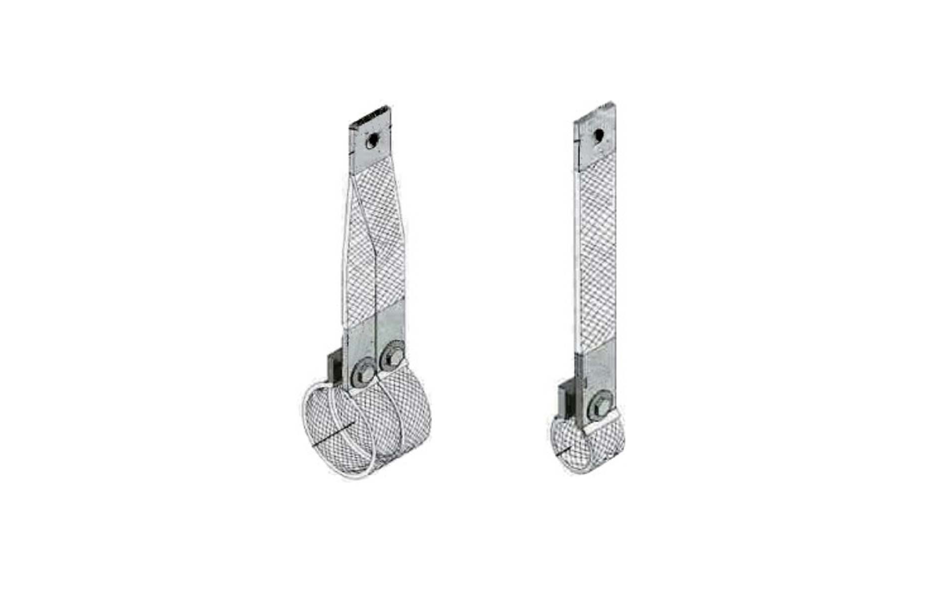
A suitable power ramp cannot correct a restrained element. Inspect refractory openings, alignment, supports, terminal straps, clamps, conductor routing, and clearance to metalwork or kiln furniture. Thermal expansion needs the movement allowed by the approved furnace design. Constraint can convert a normal temperature change into SiC heating element thermal shock damage. Record every contact point in the SiC heating element thermal shock assessment.
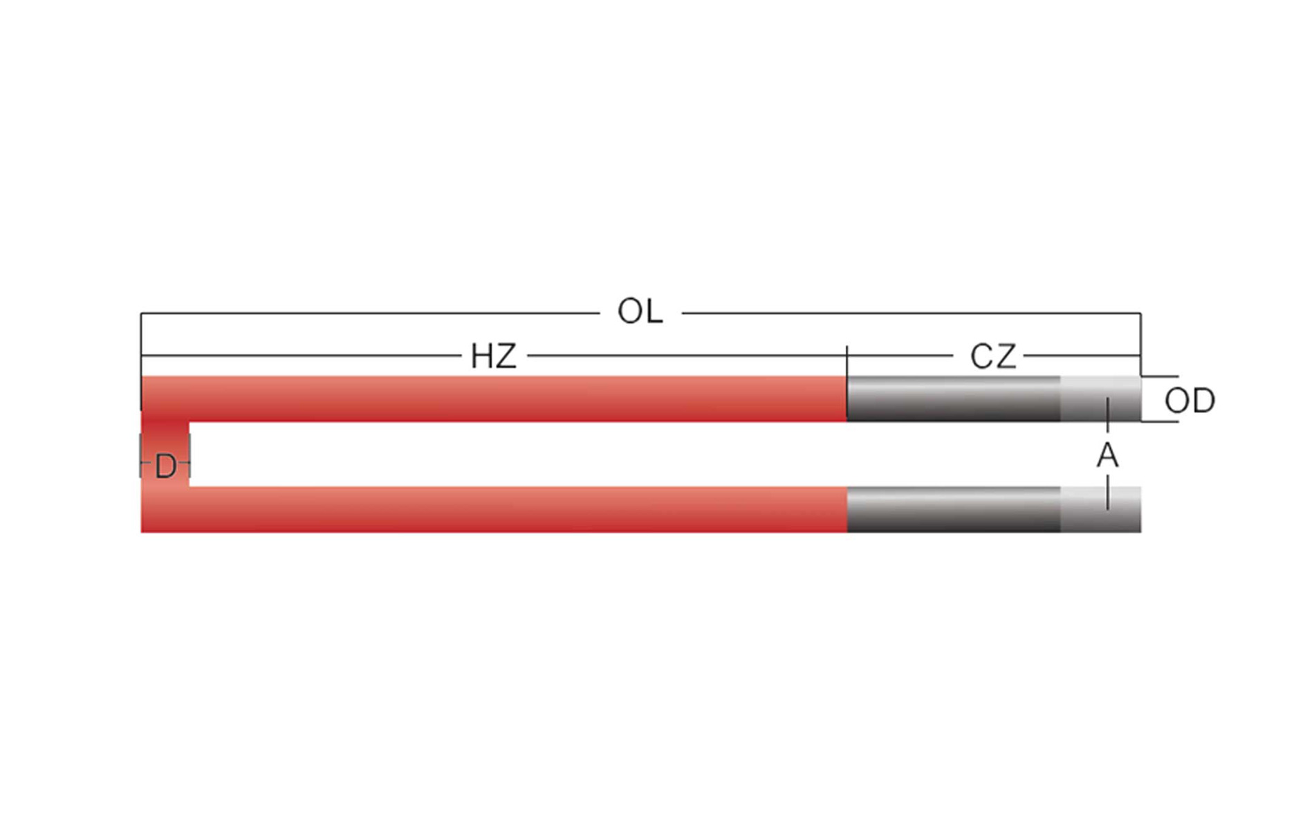
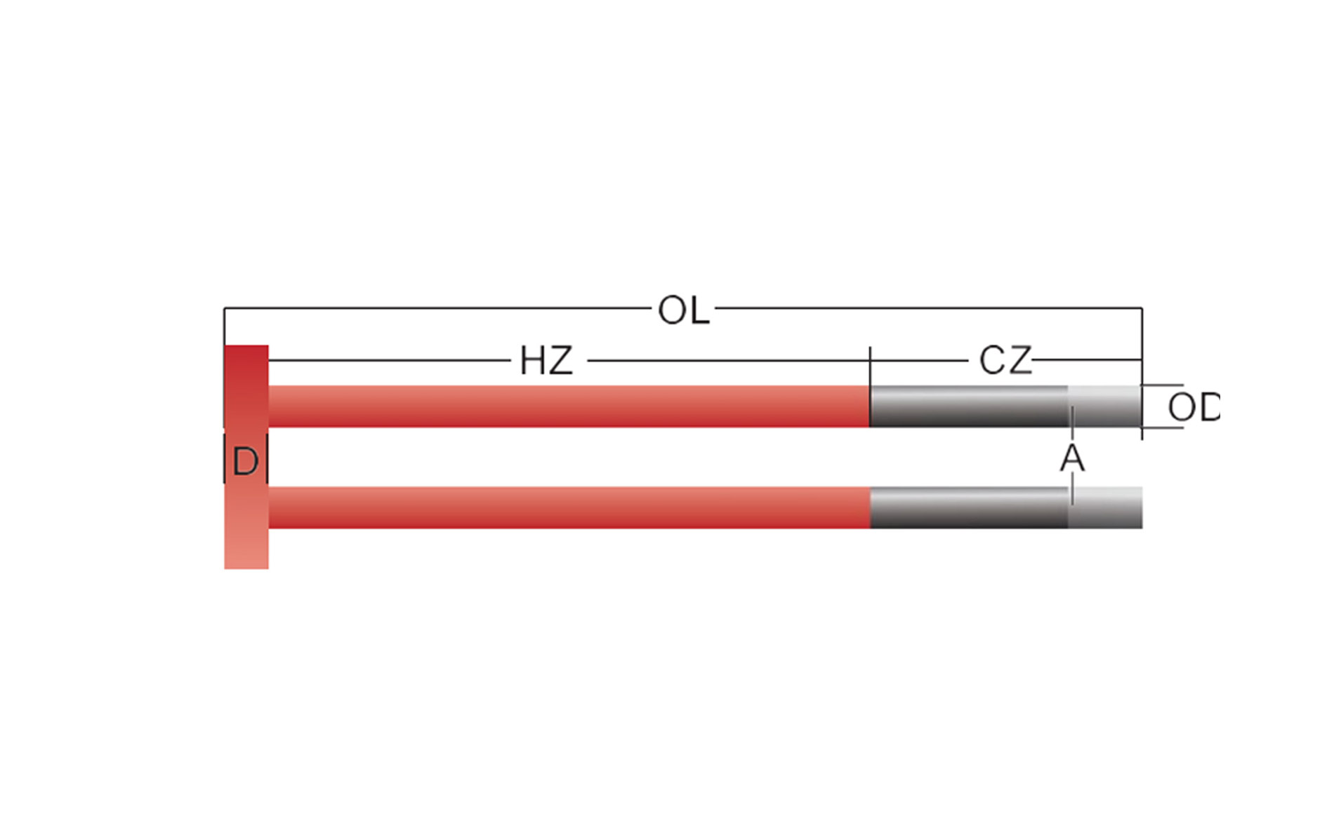
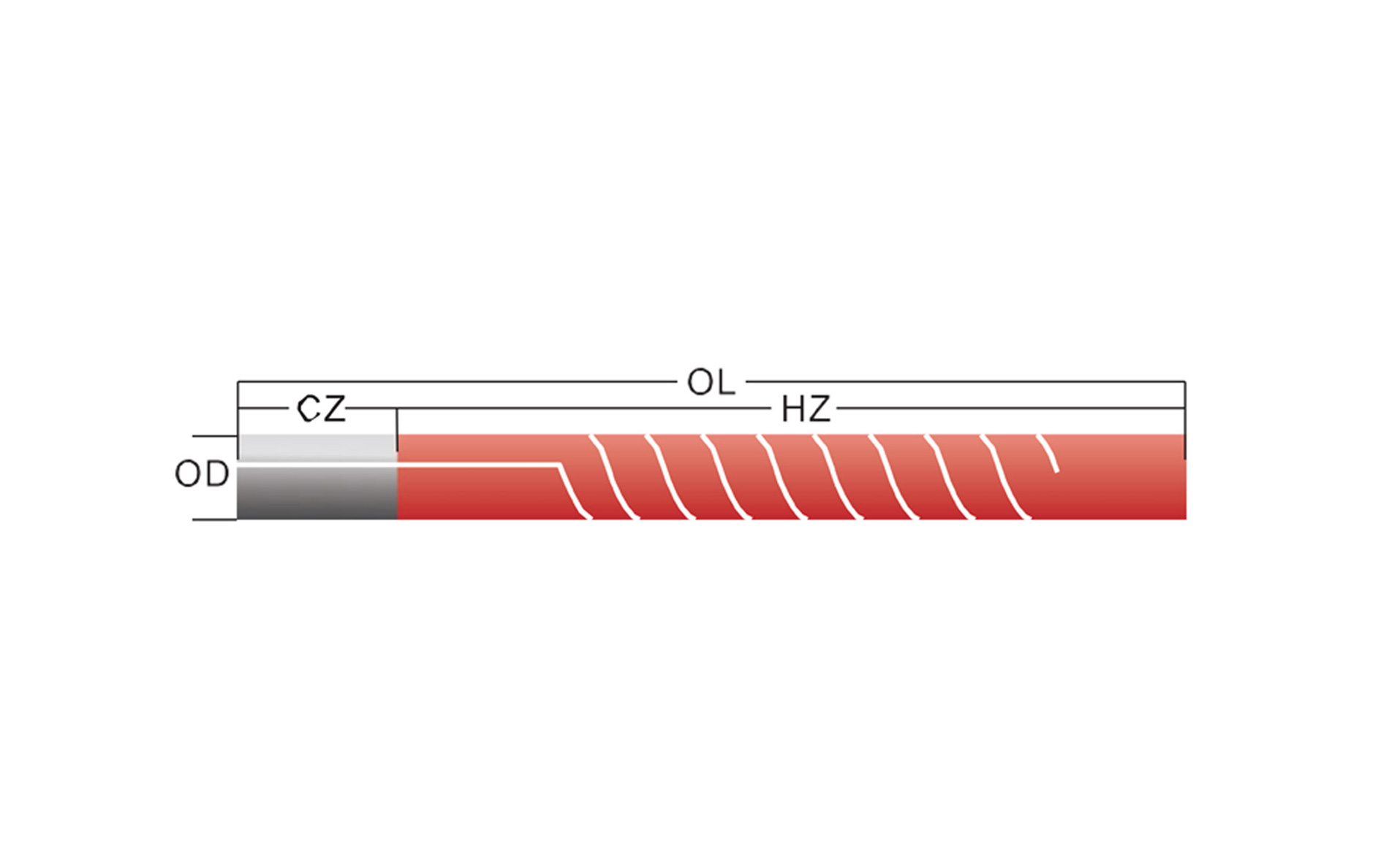
Look for contact marks, tight penetrations, repaired refractory, cable weight, rigid buswork, and unequal support. Verify hot-zone and cold-end location against the element drawing. The cold-end sizing guide explains which dimensions to record before approving a replacement.
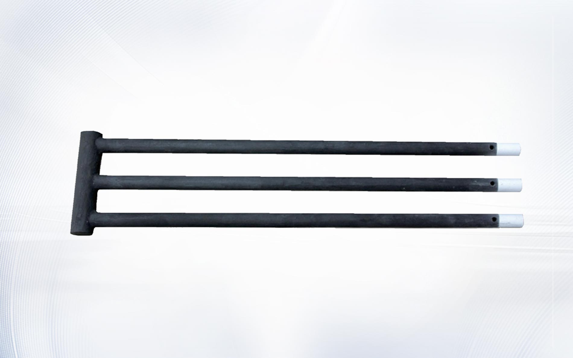
For multi-leg shapes, confirm that all legs, bridges, and terminals have the specified clearance. An installation that twists or spreads the element can add mechanical stress before the first SiC heating element thermal shock event occurs.
Write the cold-start sequence in measurable terms
A useful startup instruction identifies initial furnace condition, permitted load, atmosphere state, purge completion, output limit, temperature ramp, hold points, conditions for increasing power, and the response to abnormal feedback. “Heat slowly” is not an auditable SiC heating element thermal shock control.
Coordinate chamber-temperature ramp with power limit. At low furnace temperature, the elements can radiate strongly while the control thermocouple remains cold, so a temperature-only loop may request maximum output. Limiting initial electrical power and increasing it through approved stages can reduce local gradients.
Ramp and hold values must come from the element, refractory, furnace, atmosphere, load, and process requirements. Do not copy a generic SiC heating element thermal shock schedule into a different furnace without engineering review and commissioning evidence.
| Operating state | Required definition | Evidence to verify |
|---|---|---|
| Cold, empty furnace | Initial output limit, ramp, holds, atmosphere state | Element power, chamber temperatures, controller trend |
| Cold, loaded furnace | Approved load condition and moisture limits | Load description, exhaust and temperature response |
| Hot restart after brief trip | Restart threshold and reduced recovery output | Last valid temperatures, trip duration, controller state |
| Door or conveyor disturbance | Power response during and after the event | Door state, zone output, local temperature recovery |
| Planned cooldown | Power removal, gas flow, door and fan rules | Cooling trend and inspection record |
Treat hot restart as a separate operating state
After a brief power or sensor interruption, the refractory and elements may remain hot while the control system resets. If the controller restarts from a cold-start assumption or requests full recovery output, element temperature can change abruptly. Define a hot-restart path specifically for SiC heating element thermal shock prevention.
Use validated furnace state, trip duration, reliable temperature signals, atmosphere condition, and interlock status to decide whether a controlled restart is permitted. If state is uncertain, follow the approved safe recovery process rather than guessing from one thermocouple.
The SiC voltage control guide explains how transformer range and controller output should preserve useful control authority. Hot-restart logic must respect those electrical limits while avoiding SiC heating element thermal shock.
Control cold loads, moisture, and door events
A cold load absorbs radiation and can shadow some elements while exposed elements see a different radiating environment. Wet products or fixtures add vapour and a large transient heat demand. Define permitted load mass, arrangement, initial condition, moisture control, and loading location as part of the SiC heating element thermal shock procedure.
Door opening can combine rapid local cooling with a controller demand for more power. Trend door state and zone output together. Where the design permits, control logic may hold or limit output during an opening and use a staged recovery afterward. The responsible engineer must validate the exact SiC heating element thermal shock sequence.
Do not place cold objects against an element or direct an unapproved gas jet at it. Operating discipline around loading, inspection, and cleaning is part of SiC heating element thermal shock prevention.
Place sensors to reveal gradients, not just setpoint
One control thermocouple cannot describe every element and load surface. During commissioning or investigation, use approved temporary measurements to compare door and rear, top and bottom, exposed and shielded positions, and element power. SiC heating element thermal shock risk is often visible in differences that the main controller averages away.
Record sensor type, position, attachment or protection method, calibration, response time, and measurement uncertainty. NIST describes its thermocouple calibration services and uncertainties. Project instruments and methods must suit the actual temperature and environment.
Electrical trends matter too. Save secondary voltage, branch current, resistance basis, controller output, and tap alongside temperature. A sudden power step followed by a fracture supports a different SiC heating element thermal shock hypothesis than a fracture during a long steady hold.
Investigate a crack without assuming the cause
Before removal, photograph the fracture, supports, penetration, terminals, nearby deposits, and neighbouring elements. Record the last stable cycle and event sequence. The SiC failure guide provides a broader diagnostic checklist because SiC heating element thermal shock is only one possible cause.
For U.S. servicing work, review OSHA’s control of hazardous energy standard together with site procedures. Safe isolation and preserved evidence are both necessary before a SiC heating element thermal shock investigation proceeds.
- Break at a contact point: inspect impact, restraint, and alignment.
- Break after startup: review power step, ramp, moisture, and cold load.
- Break after door event: compare local cooling and controller response.
- Repeated break in one position: map geometry, gas flow, radiation, and support.
- Several simultaneous breaks: preserve trip, power, atmosphere, and event data.
Separate evidence from inference. A break after startup establishes timing, not mechanism. Confirm whether the element was constrained, overloaded, damaged during installation, exposed to abnormal atmosphere, or subject to a rapid gradient before concluding SiC heating element thermal shock.
Commission the procedure before production release
Verify element position, resistance grouping, wiring, transformer setting, controller limits, sensors, interlocks, purge, and load condition. Conduct a staged cold start under an approved plan, with personnel ready to stop if electrical or thermal behaviour leaves the expected range.
Compare actual output and temperature gradients with the calculation. Test only the hot-restart and disturbance cases permitted by the risk assessment. The IEC 60519-1 overview identifies the scope of general safety requirements for industrial electroheating installations. Qualified teams must apply applicable standards and site requirements throughout SiC heating element thermal shock commissioning.
After acceptance, lock or control recipe changes and retain the validated trend. An undocumented increase in ramp, output limit, or restart aggressiveness can reintroduce SiC heating element thermal shock risk months after commissioning.
Frequently asked questions
What causes thermal shock in a SiC element?
Rapid or uneven heating and cooling can create thermal stress. Startup power, hot restart, cold loads, doors, gas flow, geometry, and mechanical restraint all belong in a SiC heating element thermal shock review.
Is a slow chamber ramp always safe?
No. The element can receive high power while the chamber sensor changes slowly. Review electrical output and local gradients as well as the programmed temperature ramp.
Why is hot restart different from cold startup?
The element, refractory, load, and sensors begin at different elevated temperatures. Applying a cold-start or full-recovery command can create an abrupt change and SiC heating element thermal shock risk.
Can tight supports cause cracking?
Yes. Misalignment, tight openings, conductor weight, rigid buswork, or excessive clamping can restrain expansion and add mechanical stress.
What data should be sent after a startup crack?
Send the element drawing, position, photos before removal, ramp and output trends, trip history, voltage, current, resistance, load, atmosphere, moisture condition, installation details, service time, and quantity required.
Control the transition, not only the destination
A stable final temperature does not prove that the path was safe. Reliable operation comes from correct clearances, controlled power, separate cold-start and hot-restart logic, managed loads and atmosphere, and measurements that reveal local gradients. Those controls make SiC heating element thermal shock prevention specific and verifiable.
For replacement or new-furnace review, contact Qixiang Material with the element drawing, installation photos, electrical data, startup trend, furnace temperature, atmosphere, load, cycle, and quantity. The team can discuss suitable SiC element geometry while the responsible engineers approve the furnace procedure and control system.