A broken element is evidence, not a complete diagnosis. Replacing it without recording the fracture location, branch current, connection condition, furnace event, and nearby element behaviour can reproduce the same outage. Effective silicon carbide heating element failure analysis separates handling damage, mechanical stress, electrical overload, atmosphere effects, thermal shock, and normal resistance development.
This guide gives furnace maintenance teams and engineers a nine-cause silicon carbide heating element failure checklist. It focuses on evidence that can be collected before removal, during inspection, and after safe replacement so the corrective action addresses the most likely mechanism.
Preserve evidence before removing the element
First put the furnace in its approved safe maintenance state. Photograph the element position, supports, wall penetrations, terminal straps, clamps, conductor routing, deposits, and fracture faces before anything is moved. A useful silicon carbide heating element failure record also captures the alarm sequence, controller output, voltage, current, temperature, load, atmosphere, and recent maintenance.
- Identify the furnace, zone, branch, and exact element position.
- Record whether the break is in the hot zone, transition, cold end, or terminal area.
- Compare neighbouring elements and both sides of the furnace.
- Save trend data from before, during, and after the event.
- Note any cold start, hot restart, power interruption, door event, load change, or atmosphere upset.
Do not clean the evidence too early. Deposits, discoloration, local melting, loose hardware, and contact marks can distinguish one silicon carbide heating element failure mechanism from another.
1. Impact or handling damage
Damage can begin during unpacking, storage, lifting, insertion, or later work around the furnace. A small impact may create a crack that opens during heating. Suspect handling-related silicon carbide heating element failure when a new element breaks soon after installation, the fracture is near a contact point, or packaging and receiving records show an abnormal event.
Check whether the element was carried by one end, rested across an unsupported span, struck against the casing, or used as a support for tools or conductors. Inspect the packaging of other units from the same delivery. Corrective action should address the handling route and support method, not merely replace the part. Record that conclusion in the silicon carbide heating element failure file.
2. Mechanical constraint at the wall or support
An element needs the clearance and support defined by the furnace design. Tight refractory openings, misaligned holes, rigid conductors, cable weight, excessive clamping force, or restrained thermal expansion can load the ceramic. A silicon carbide heating element failure near a penetration or terminal often warrants a dimensional and alignment check.
Measure both openings and compare their centreline with the element drawing. Look for repaired refractory, deposits, distorted metalwork, and marks showing contact. Use the cold-end sizing guide to review hot-zone location, wall passage, external clearance, and terminal access.
Do not enlarge an opening or change a support without responsible engineering approval. The corrective action for a mechanically induced silicon carbide heating element failure must preserve electrical clearances, atmosphere control, insulation, and furnace integrity.
3. Thermal shock or an unsuitable restart
A rapid temperature change can create damaging thermal gradients in the element or furnace assembly. Review cold-start ramps, hot restarts, door openings, cold load insertion, atmosphere changes, and controller recovery. Thermal-shock silicon carbide heating element failure is more credible when the event follows a sudden operating change rather than a long stable hold.
Compare the actual recipe and output trend with the approved sequence. A controller may jump to high output after a brief sensor interruption or trip even though the displayed chamber temperature changes slowly. Correct the restart and interlock logic before returning the zone to normal service, then retain the test in the silicon carbide heating element failure report.
4. Excessive element surface loading
Too much power for the available hot-zone surface can drive element temperature beyond what the application allows. Review watts per element, hot-zone dimensions, surface area, chamber temperature, atmosphere, load radiation, and element spacing. A silicon carbide heating element failure in a repeatedly overheated region may reflect local surface loading rather than total furnace kilowatts.
Use measured voltage, current, and resistance to reconstruct delivered power. The SiC power calculation guide explains how to connect zone duty with element-level power and surface area. Check every operating recipe, not only the normal setpoint.
| Evidence | Likely review path | Do not assume |
|---|---|---|
| Break near wall penetration | Alignment, clearance, restraint, cold-end location | All fractures are thermal shock |
| Hot or discoloured terminal | Contact pressure, strap, clamp, current, cooling | More voltage will fix the connection |
| One low-current branch | Resistance, open element, grouping, conductor path | Every element aged equally |
| Damage after atmosphere upset | Gas composition, leaks, purge, deposits, temperature | Nominal atmosphere equals local atmosphere |
| Zone at maximum output | Resistance trend, tap range, loss, load, sensor | The elements alone caused slow recovery |
5. Unsuitable furnace atmosphere or contamination
Gas composition, moisture, leakage, process vapours, deposits, and temperature affect element behaviour. Record the actual atmosphere and event history at the element position. A silicon carbide heating element failure attributed to “oxidation” without gas, temperature, and deposit evidence is too vague to support a corrective action.
Inspect seals, purge sequence, exhaust balance, load chemistry, binders, cleaning agents, and any material that can contact or condense on the element. Compare affected and unaffected positions. Changes concentrated near an inlet, door, or load surface can reveal a local exposure that average furnace data misses in a silicon carbide heating element failure investigation.
The U.S. Department of Energy’s process heating resources support evaluating the complete process-heating system. For silicon carbide heating element failure work, that includes load, enclosure, atmosphere, heat source, and control—not the rod alone.
6. Loose, undersized, or overheated terminal connections
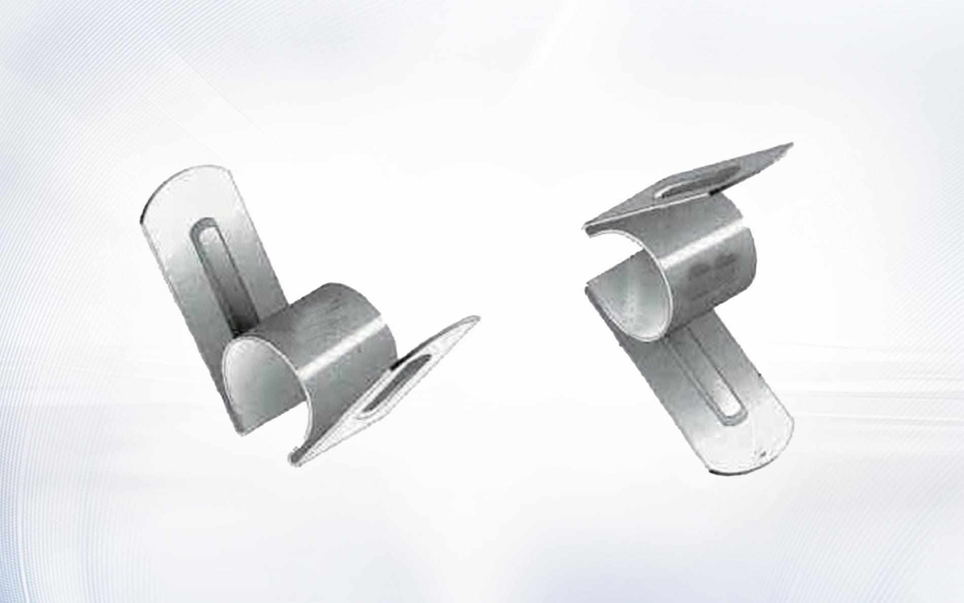
Poor contact creates local resistance and heat. Look for loose clamps, damaged straps, discoloration, oxidation, melted conductor strands, stiff routing, and unequal temperature at comparable terminals. A connection-related silicon carbide heating element failure may start outside the hot zone and be missed if inspection stops at the broken rod.
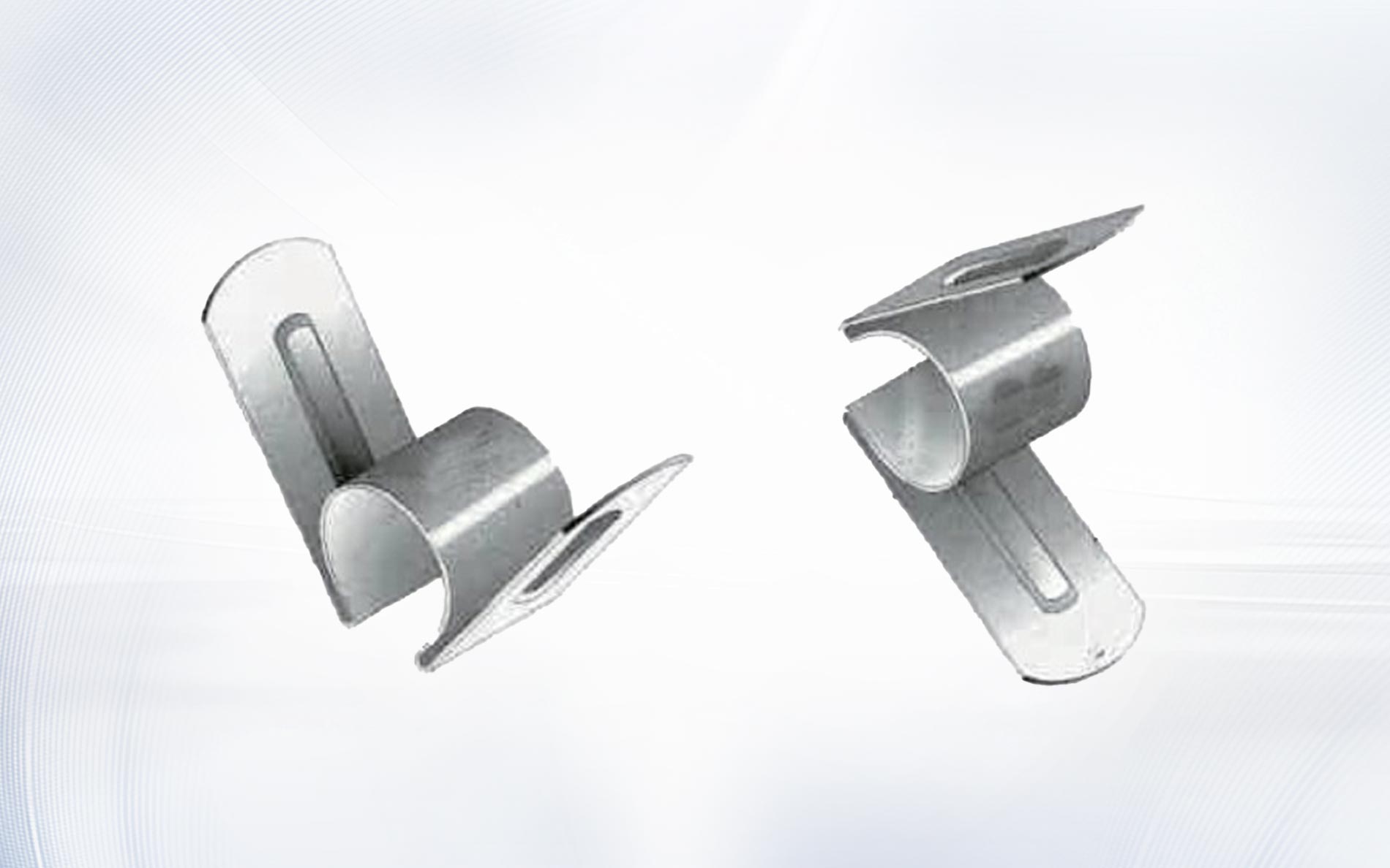
Check the approved aluminum conductive strip and heating rod clamp specification against the installed hardware. Record dimensions and condition. Tightening force, contact method, conductor support, and inspection frequency must follow the responsible design and supplier instructions.
Use voltage drop and thermal observations cautiously and only under approved procedures. The OSHA electrical standards page is a starting point for U.S. workplace requirements; qualified personnel must control energized work and the complete silicon carbide heating element failure investigation.

7. Resistance mismatch or incorrect circuit grouping
Series elements carry the same current, but voltage and power divide according to resistance. Parallel branches share voltage, while current changes with branch resistance. A replacement of unsuitable resistance can shift power distribution and lead to local silicon carbide heating element failure even when total zone current appears acceptable.
Measure and record each approved element or branch at the specified condition. Compare the as-built circuit with the SiC wiring diagram. The current calculation guide helps trace unequal branch current back to resistance and grouping.
Do not mix new and aged elements in a string or branch without an approved matching strategy. Document every regrouping so the next silicon carbide heating element failure review begins with the actual circuit, not an obsolete drawing.
8. Hot-zone or cold-end misplacement
If part of the hot zone sits inside the refractory penetration, heat concentrates where it is difficult to dissipate and inspect. If the cold end extends too far into the chamber, the designed radiating area no longer aligns with the load. Dimensional mismatch can contribute to silicon carbide heating element failure and uneven furnace performance.
Mark both furnace hot faces on the element drawing and verify installed position before energization. Compare overall length, hot-zone length, both cold ends, diameter, and terminal location. Do not approve a replacement from overall length or a product photograph alone.
9. Resistance growth beyond the usable voltage range
Service resistance normally changes over time. Eventually the available transformer and controller range may no longer deliver required power, but slow recovery alone does not prove end of life. Review measured resistance, voltage, current, load, losses, sensor accuracy, and connections before classifying a silicon carbide heating element failure as normal aging.
The voltage control guide explains how to establish new-element and higher-resistance operating windows. Use comparable production conditions and a defined replacement threshold. Unexplained tap changes destroy valuable trend evidence.
When replacement is justified, decide whether to replace one element, a matched string, or a larger group according to the approved circuit strategy. Record the removed resistance and cause category in the silicon carbide heating element failure history.
Turn findings into corrective action
Separate direct evidence, calculation, inference, and unknowns. A cracked part beside a tight opening is evidence; saying the opening caused the crack is a hypothesis until dimensions, contact marks, alignment, and event history support it. A defensible silicon carbide heating element failure report states why alternative causes were accepted or rejected.
The IEC 60519-1 overview describes the scope of general safety requirements for industrial electroheating installations. Applicable standards, local requirements, and the project risk assessment govern the silicon carbide heating element failure work.
- Contain the immediate risk and inspect related positions.
- Identify the most probable mechanism and contributing conditions.
- Correct the installation, control, atmosphere, electrical, or handling issue.
- Define a verification measurement after restart.
- Update drawings, recipes, inspection standards, and purchasing data.
NIST Technical Note 1297 explains general principles for expressing measurement uncertainty. Apply a suitable project method when resistance, dimensions, current, or temperature are used to distinguish competing silicon carbide heating element failure hypotheses.
Frequently asked questions
Why did a new SiC element break soon after installation?
Check shipping and handling, opening alignment, support, conductor load, clamping, resistance matching, circuit grouping, and startup history. Early silicon carbide heating element failure is not automatically a manufacturing defect.
Does a crack always mean thermal shock?
No. Impact, mechanical restraint, misalignment, local overheating, atmosphere effects, and connection problems can also contribute. Fracture position and event data are essential.
Should one failed element or the whole group be replaced?
Use the approved resistance-matching and circuit strategy. The answer depends on series or parallel grouping, measured resistance, service history, available voltage range, and the diagnosed silicon carbide heating element failure cause.
Can higher voltage restore a weak zone?
Only when resistance growth and the approved operating envelope justify it. Higher voltage does not repair open elements, poor connections, insulation loss, sensor error, or unsuitable loads.
What should be sent to the supplier after a failure?
Send the element drawing, position, photos before removal, fracture details, resistance, voltage and current trends, wiring, connection photos, temperature, atmosphere, cycle, load, event sequence, service time, and quantity required. This evidence supports a useful silicon carbide heating element failure review.
Replace the cause, not only the broken part
The most productive investigation begins before the element is disturbed and ends after the corrective action is verified under representative operation. A structured silicon carbide heating element failure record turns an outage into evidence for safer installation, better control, clearer purchasing specifications, and more reliable maintenance.
For a replacement review, contact Qixiang Material with the drawing, photos, resistance and circuit data, operating history, temperature, atmosphere, cycle, and quantity. The team can discuss suitable SiC element geometry and connection accessories while the responsible engineers determine and approve the system-level corrective action.